3. SIGNALS AND WIRING
3 - 68
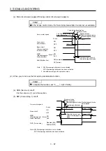
(c) Alarm occurrence
The operation status during an alarm is the same as section 3.8.
(d) Both main and control circuit power supplies off
It is the same as (1) (d) of this section.
(e) Main circuit power supply off during control circuit power supply on
Dynamic brake
Dynamic brake
+ Electromagnetic brake
Electromagnetic brake
Operation delay time of
the electromagnetic brake
MBR
(Electromagnetic
brake interlock)
(Note 2)
Base circuit
Alarm
[AL.10 Undervoltage]
No alarm
Alarm
Servo motor speed
Approx. 10 ms
(Note 1)
ON
OFF
ON
OFF
Main circuit
power supply
ON
OFF
0 r/min
Note 1. Variable according to the operation status.
2.
ON:
Electromagnetic
brake is not activated.
OFF: Electromagnetic brake has been activated.
Summary of Contents for MR-J4-100A
Page 9: ...A 8 MEMO ...
Page 61: ...1 FUNCTIONS AND CONFIGURATION 1 44 MEMO ...
Page 67: ...2 INSTALLATION 2 6 MEMO ...
Page 137: ...3 SIGNALS AND WIRING 3 70 MEMO ...
Page 261: ...6 NORMAL GAIN ADJUSTMENT 6 24 MEMO ...
Page 291: ...7 SPECIAL ADJUSTMENT FUNCTIONS 7 30 MEMO ...
Page 299: ...8 TROUBLESHOOTING 8 8 MEMO ...
Page 319: ...9 OUTLINE DRAWINGS 9 20 MEMO ...
Page 461: ...12 ABSOLUTE POSITION DETECTION SYSTEM 12 36 MEMO ...
Page 511: ...14 COMMUNICATION FUNCTION 14 38 MEMO ...
Page 559: ...16 USING A DIRECT DRIVE MOTOR 16 20 MEMO ...
Page 583: ...17 FULLY CLOSED LOOP SYSTEM 17 24 MEMO ...
Page 621: ...APPENDIX App 38 ...
Page 639: ......


