4. STARTUP
4 - 6
4.1.3 Surrounding environment
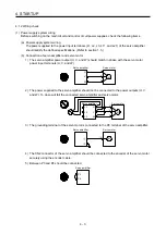
(1) Cable routing
(a) The wiring cables should not be stressed.
(b) The encoder cable should not be used in excess of its bending life. (Refer to section 10.4.)
(c) The connector of the servo motor should not be stressed.
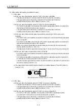
(2) Environment
Signal cables and power cables are not shorted by wire offcuts, metallic dust or the like.
4.2 Startup in position control mode
Make a startup in accordance with section 4.1. This section provides the methods specific to the position
control mode.
4.2.1 Power on and off procedures
(1) Power-on
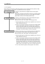
Switch power on in the following procedure. Always follow this procedure at power-on.
1) Switch off SON (Servo-on).
2) Make sure that a command pulse train is not input.
3) Switch on the main circuit power supply and control circuit power supply.
When main circuit power/control circuit power is switched on, the display shows "C (Cumulative
feedback pulses)", and in 2 s later, shows data.
In the absolute position detection system, first power-on results in [AL. 25 Absolute position
erased] and the servo system cannot be switched on. The alarm can be deactivated by then
switching power off once and on again.
Also, if power is switched on at the servo motor speed of 3000 r/min or higher, position mismatch
may occur due to external force or the like. Power must therefore be switched on when the servo
motor is at a stop.
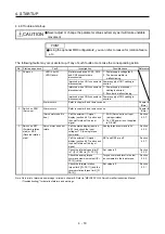
(2) Power-off
1) Make sure that a command pulse train is not input.
2) Switch off SON (Servo-on).
3) Switch off the main circuit power supply and control circuit power supply.
Summary of Contents for MR-J4-100A
Page 9: ...A 8 MEMO ...
Page 61: ...1 FUNCTIONS AND CONFIGURATION 1 44 MEMO ...
Page 67: ...2 INSTALLATION 2 6 MEMO ...
Page 137: ...3 SIGNALS AND WIRING 3 70 MEMO ...
Page 261: ...6 NORMAL GAIN ADJUSTMENT 6 24 MEMO ...
Page 291: ...7 SPECIAL ADJUSTMENT FUNCTIONS 7 30 MEMO ...
Page 299: ...8 TROUBLESHOOTING 8 8 MEMO ...
Page 319: ...9 OUTLINE DRAWINGS 9 20 MEMO ...
Page 461: ...12 ABSOLUTE POSITION DETECTION SYSTEM 12 36 MEMO ...
Page 511: ...14 COMMUNICATION FUNCTION 14 38 MEMO ...
Page 559: ...16 USING A DIRECT DRIVE MOTOR 16 20 MEMO ...
Page 583: ...17 FULLY CLOSED LOOP SYSTEM 17 24 MEMO ...
Page 621: ...APPENDIX App 38 ...
Page 639: ......


