4. STARTUP
4 - 37
4.5.8 Output signal (DO) forced output
POINT
When the servo system is used in a vertical lift application, turning on MBR
(Electromagnetic brake interlock) by the DO forced output after assigning it to
connector CN1 will release the electromagnetic brake, causing a drop. Take
drop preventive measures on the machine side.
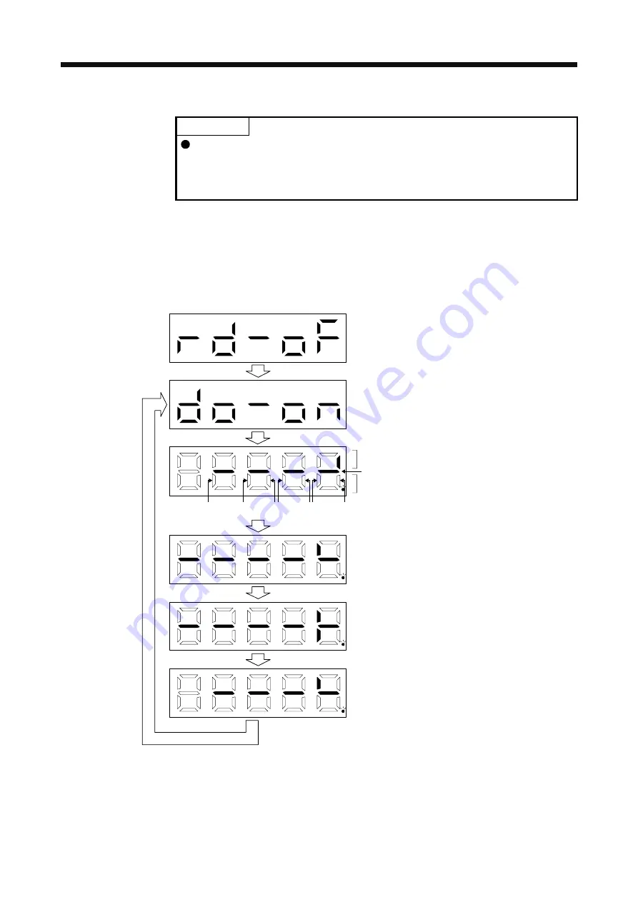
Output signals can be switched on/off forcibly independently of the servo status. This function is used for
output signal wiring check, etc. This operation must be performed in the servo off state by turning off the
SON (Servo-on).
Operation
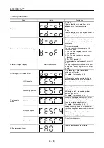
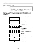
Call the display screen shown after power-on. Using the "MODE" button, show the diagnostic screen.
……
……
……
……
……
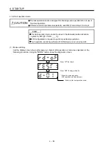
Switch on/off the signal below the lit segment.
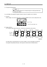
Indicates on/off of output signal. Definitions of on/off
are the same as those for the external I/O signals.
(Light on: on, light off: off)
Press "UP" three times.
Press "SET" for longer than 2 s.
CN1
33
CN1
48
CN1
22
CN1
25
CN1
23
CN1
24
CN1
49
Press "MODE" once.
Press "UP" once.
CN1-24 switches on.
(Between CN1-24 and DOCOM are connected.)
The lit LED moves to the upper LED of CN1-24.
Press "DOWN" once.
CN1-24 switches off.
Press "SET" for longer than 2 s.
Always lit
Summary of Contents for MR-J4-100A
Page 9: ...A 8 MEMO ...
Page 61: ...1 FUNCTIONS AND CONFIGURATION 1 44 MEMO ...
Page 67: ...2 INSTALLATION 2 6 MEMO ...
Page 137: ...3 SIGNALS AND WIRING 3 70 MEMO ...
Page 261: ...6 NORMAL GAIN ADJUSTMENT 6 24 MEMO ...
Page 291: ...7 SPECIAL ADJUSTMENT FUNCTIONS 7 30 MEMO ...
Page 299: ...8 TROUBLESHOOTING 8 8 MEMO ...
Page 319: ...9 OUTLINE DRAWINGS 9 20 MEMO ...
Page 461: ...12 ABSOLUTE POSITION DETECTION SYSTEM 12 36 MEMO ...
Page 511: ...14 COMMUNICATION FUNCTION 14 38 MEMO ...
Page 559: ...16 USING A DIRECT DRIVE MOTOR 16 20 MEMO ...
Page 583: ...17 FULLY CLOSED LOOP SYSTEM 17 24 MEMO ...
Page 621: ...APPENDIX App 38 ...
Page 639: ......


