5. PARAMETERS
5 - 40
Control
mode
No./symbol/
name
Setting
digit
Function
Initial
value
[unit]
P S T
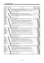
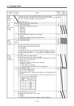
PC20
*SNO
Station No.
setting
Set a station No. of the servo amplifier for RS-422 and USB communication.
Always set one station to one axis of the servo amplifier. Setting one station number
to two or more stations will disable a normal communication.
Setting range: 0 to 31
0
[Station]
Select the details of RS-422 communication function.
_ _ _ x For manufacturer setting
0h
_ _ x _ RS-422 communication baud rate selection
0: 9600 [bps]
1: 19200 [bps]
2: 38400 [bps]
3: 57600 [bps]
4: 115200 [bps]
0h
_ x _ _ RS-422 communication response delay time selection
0: Disabled
1: Enabled (responding after 800
μ
s or longer delay time)
0h
PC21
*SOP
RS-422
communication
function
selection
x _ _ _ For manufacturer setting
0h
_ _ _ x For manufacturer setting
0h
_ _ x _
0h
_ x _ _
0h
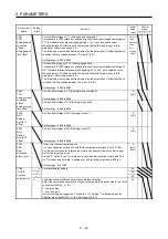
PC22
*COP1
Function
selection C-1 x _ _ _ Encoder cable communication method selection
Select the encoder cable communication method.
0: Two-wire type
1: Four-wire type
If the setting is incorrect, [AL. 16 Encoder initial communication error 1] or [AL. 20
Encoder normal communication error 1] occurs. Setting "1" will trigger [AL. 37] while
"Fully closed loop control mode (_ _ 1 _)" is selected in [Pr. PA01] (except MR-J4-
_A_-RJ).
0h
PC23
*COP2
Function
selection C-2
_ _ _ x Servo-lock selection at speed control stop
Select the servo-lock selection at speed control stop.
In the speed control mode, the servo motor shaft can be locked to prevent the shaft
from being moved by an external force.
0: Enabled (servo-lock)
The operation to maintain the stop position is performed.
1: Disabled (no servo-lock)
The stop position is not maintained.
The control to make the speed 0 r/min or 0 mm/s is performed.
0h
_ _ x _ For manufacturer setting
0h
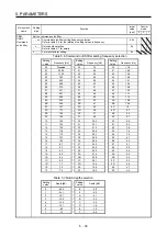
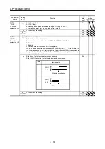
_ x _ _ VC/VLA voltage averaging selection
Select the VC/VLA voltage average.
Set the filtering time when VC (Analog speed command) or VLA (Analog speed limit)
is imported.
Set 0 to vary the speed to voltage fluctuation in real time. Increase the set value to
vary the speed slower to voltage fluctuation.
0h
Setting
value
Filtering time [ms]
0
0
1
0.444
2
0.888
3
1.777
4
3.555
5
7.111
x _ _ _ Speed limit selection at torque control
Select the speed limit selection at torque control.
0: Enabled
1: Disabled
Do not use this function except when configuring an external speed loop.
0h
Summary of Contents for MR-J4-100A
Page 9: ...A 8 MEMO ...
Page 61: ...1 FUNCTIONS AND CONFIGURATION 1 44 MEMO ...
Page 67: ...2 INSTALLATION 2 6 MEMO ...
Page 137: ...3 SIGNALS AND WIRING 3 70 MEMO ...
Page 261: ...6 NORMAL GAIN ADJUSTMENT 6 24 MEMO ...
Page 291: ...7 SPECIAL ADJUSTMENT FUNCTIONS 7 30 MEMO ...
Page 299: ...8 TROUBLESHOOTING 8 8 MEMO ...
Page 319: ...9 OUTLINE DRAWINGS 9 20 MEMO ...
Page 461: ...12 ABSOLUTE POSITION DETECTION SYSTEM 12 36 MEMO ...
Page 511: ...14 COMMUNICATION FUNCTION 14 38 MEMO ...
Page 559: ...16 USING A DIRECT DRIVE MOTOR 16 20 MEMO ...
Page 583: ...17 FULLY CLOSED LOOP SYSTEM 17 24 MEMO ...
Page 621: ...APPENDIX App 38 ...
Page 639: ......


