7. SPECIAL ADJUSTMENT FUNCTIONS
7 - 5
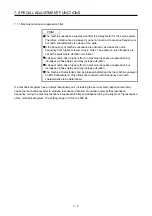
7.1.2 Adaptive filter II
POINT
The machine resonance frequency which adaptive filter II (adaptive tuning) can
respond to is about 100 Hz to 2.25 kHz. As for the resonance frequency out of
the range, set manually.
When adaptive tuning is executed, vibration sound increases as an excitation
signal is forcibly applied for several seconds.
When adaptive tuning is executed, machine resonance is detected for a
maximum of 10 seconds and a filter is generated. After filter generation, the
adaptive tuning mode automatically shifts to the manual setting.
Adaptive tuning generates the optimum filter with the currently set control gains.
If vibration occurs when the response setting is increased, execute adaptive
tuning again.
During adaptive tuning, a filter having the best notch depth at the set control
gain is generated. To allow a filter margin against machine resonance, increase
the notch depth in the manual setting.
Adaptive vibration suppression control may provide no effect on a mechanical
system which has complex resonance characteristics.
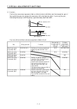
(1) Function
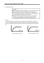
Adaptive filter II (adaptive tuning) is a function in which the servo amplifier detects machine vibration for
a predetermined period of time and sets the filter characteristics automatically to suppress mechanical
system vibration. Since the filter characteristics (frequency, depth) are set automatically, you need not
be conscious of the resonance frequency of a mechanical system.
R
e
sponse of
mechanical system
N
o
tc
h
depth
Machine resonance point
Notch frequency
Frequency
Frequency
R
e
sponse of
mechanical system
N
o
tc
h
depth
Machine resonance point
Notch frequency
Frequency
Frequency
When machine resonance is large and
frequency is low
When machine resonance is small and
frequency is high
(2) Parameter
Select how to set the filter tuning in [Pr. PB01 Adaptive tuning mode (adaptive filter II)].
[Pr. PB01]
Filter tuning mode selection
0 0 0
0
1
2
Setting
value
Filter tuning mode selection
Disabled
Automatic setting
Manual setting
PB13/PB14
Automatically set parameter
Summary of Contents for MR-J4-100A
Page 9: ...A 8 MEMO ...
Page 61: ...1 FUNCTIONS AND CONFIGURATION 1 44 MEMO ...
Page 67: ...2 INSTALLATION 2 6 MEMO ...
Page 137: ...3 SIGNALS AND WIRING 3 70 MEMO ...
Page 261: ...6 NORMAL GAIN ADJUSTMENT 6 24 MEMO ...
Page 291: ...7 SPECIAL ADJUSTMENT FUNCTIONS 7 30 MEMO ...
Page 299: ...8 TROUBLESHOOTING 8 8 MEMO ...
Page 319: ...9 OUTLINE DRAWINGS 9 20 MEMO ...
Page 461: ...12 ABSOLUTE POSITION DETECTION SYSTEM 12 36 MEMO ...
Page 511: ...14 COMMUNICATION FUNCTION 14 38 MEMO ...
Page 559: ...16 USING A DIRECT DRIVE MOTOR 16 20 MEMO ...
Page 583: ...17 FULLY CLOSED LOOP SYSTEM 17 24 MEMO ...
Page 621: ...APPENDIX App 38 ...
Page 639: ......


