10. CHARACTERISTICS
10 - 10
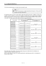
10.3.2 Permissible load to motor inertia when the dynamic brake is used
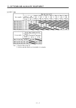
Use the dynamic brake under the load to motor inertia ratio indicated in the following table. If the load inertia
moment is higher than this value, the dynamic brake may burn. If the load to motor inertia ratio exceeds the
indicated value, contact your local sales office.
The values of the permissible load to motor inertia ratio in the table are the values at the maximum rotation
speed of the servo motor.
(a) 200 V class
Servo motor
Permissible load to motor inertia
ratio [multiplier]
Servo
motor
Permissible load to motor inertia
ratio [multiplier]
HG-KR053
HG-UR72
HG-KR13
HG-UR152
30
HG-KR23 30
HG-UR202
HG-KR43
HG-UR352
16
HG-KR73
HG-UR502
15
HG-MR053 35
HG-RR103
HG-MR13
HG-RR153
30
HG-MR23
HG-RR203
16
HG-MR43
32
HG-RR353
HG-MR73
HG-RR503
15
HG-SR51
HG-JR53
HG-SR81
HG-JR73
HG-SR121
HG-JR103
HG-SR201
30
HG-JR203
30
HG-SR301
16
HG-JR353
16 (Note 2)
HG-SR421
15
HG-JR503
15 (Note 2)
HG-SR52
HG-JR703
11 (Note 2)
HG-SR102
30
HG-JR903
18 (Note 2)
HG-SR152
HG-JR11K1M
HG-SR202
21
HG-JR15K1M
10 (Note 2)
HG-SR352
HG-JR22K1M
20 (Note 2)
HG-SR502
13 (Note 1)
HG-SR702
5 (Note 1)
Note 1. The permissible load to motor inertia ratio is 15 at the rated rotation speed.
2. The permissible load to motor inertia ratio is 30 at the rated rotation speed.
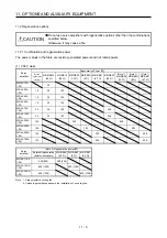
(b) 400 V class
Servo motor
Permissible load to motor inertia
ratio [multiplier (×1)]
Servo
motor
Permissible load to motor inertia
ratio [multiplier (×1)]
HG-SR524 5
(15)
HG-JR534
HG-SR1024
HG-JR734
HG-SR1524
5 (17)
HG-JR1034
HG-SR2024
HG-JR1534
HG-SR3524
HG-JR2034
30 (30)
HG-SR5024
5 (15)
HG-JR3534
20 (30) (Note)
HG-SR7024
HG-JR5034
15
(30)
HG-JR7034
11
(30)
HG-JR9034
18
(30)
HG-JR11K1M4
HG-JR15K1M4
10 (30)
HG-JR22K1M4
20
(30)
Note. When the maximum torque is increased to 400%, the permissible load to motor inertia ratio at the maximum speed
of the servo motor is 25 times.
Summary of Contents for MR-J4-100A
Page 9: ...A 8 MEMO ...
Page 61: ...1 FUNCTIONS AND CONFIGURATION 1 44 MEMO ...
Page 67: ...2 INSTALLATION 2 6 MEMO ...
Page 137: ...3 SIGNALS AND WIRING 3 70 MEMO ...
Page 261: ...6 NORMAL GAIN ADJUSTMENT 6 24 MEMO ...
Page 291: ...7 SPECIAL ADJUSTMENT FUNCTIONS 7 30 MEMO ...
Page 299: ...8 TROUBLESHOOTING 8 8 MEMO ...
Page 319: ...9 OUTLINE DRAWINGS 9 20 MEMO ...
Page 461: ...12 ABSOLUTE POSITION DETECTION SYSTEM 12 36 MEMO ...
Page 511: ...14 COMMUNICATION FUNCTION 14 38 MEMO ...
Page 559: ...16 USING A DIRECT DRIVE MOTOR 16 20 MEMO ...
Page 583: ...17 FULLY CLOSED LOOP SYSTEM 17 24 MEMO ...
Page 621: ...APPENDIX App 38 ...
Page 639: ......


