11. OPTIONS AND AUXILIARY EQUIPMENT
11 - 54
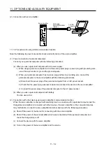
(2) Connection with servo amplifier
To USB
connector
Servo amplifier
USB cable
MR-J3USBCBL3M
(Option)
Personal computer
CN5
11.7.3 Precautions for using USB communication function
Note the following to prevent an electric shock and malfunction of the servo amplifier.
(1) Power connection of personal computers
Connect your personal computer with the following procedures.
(a) When you use a personal computer with AC power supply
1) When using a personal computer with a three-core power plug or power plug with grounding wire,
use a three-pin socket or ground the grounding wire.
2) When your personal computer has two-core plug and has no grounding wire, connect the
personal computer to the servo amplifier with the following procedures.
a) Disconnect the power plug of the personal computer from an AC power socket.
b) Check that the power plug was disconnected and connect the device to the servo amplifier.
c) Connect the power plug of the personal computer to the AC power socket.
(b) When you use a personal computer with battery
You can use as it is.
(2) Connection with other devices using servo amplifier communication function
When the servo amplifier is charged with electricity due to connection with a personal computer and the
charged servo amplifier is connected with other devices, the servo amplifier or the connected devices
may malfunction. Connect the servo amplifier and other devices with the following procedures.
(a) Shut off the power of the device for connecting with the servo amplifier.
(b) Shut off the power of the servo amplifier which was connected with the personal computer and
check the charge lamp is off.
(c) Connect the device with the servo amplifier.
(d) Turn on the power of the servo amplifier and the device.
Summary of Contents for MR-J4-100A
Page 9: ...A 8 MEMO ...
Page 61: ...1 FUNCTIONS AND CONFIGURATION 1 44 MEMO ...
Page 67: ...2 INSTALLATION 2 6 MEMO ...
Page 137: ...3 SIGNALS AND WIRING 3 70 MEMO ...
Page 261: ...6 NORMAL GAIN ADJUSTMENT 6 24 MEMO ...
Page 291: ...7 SPECIAL ADJUSTMENT FUNCTIONS 7 30 MEMO ...
Page 299: ...8 TROUBLESHOOTING 8 8 MEMO ...
Page 319: ...9 OUTLINE DRAWINGS 9 20 MEMO ...
Page 461: ...12 ABSOLUTE POSITION DETECTION SYSTEM 12 36 MEMO ...
Page 511: ...14 COMMUNICATION FUNCTION 14 38 MEMO ...
Page 559: ...16 USING A DIRECT DRIVE MOTOR 16 20 MEMO ...
Page 583: ...17 FULLY CLOSED LOOP SYSTEM 17 24 MEMO ...
Page 621: ...APPENDIX App 38 ...
Page 639: ......

