11. OPTIONS AND AUXILIARY EQUIPMENT
11 - 84
11.17 External dynamic brake
CAUTION
Use an external dynamic brake for a servo amplifier of MR-J4-11KA(-RJ) to MR-
J4-22KA(-RJ) and MR-J4-11KA4(-RJ) to MRJ4-22KA4(-RJ). Failure to do so will
cause an accident because the servo motor does not stop immediately but coasts
at an alarm occurrence for which the servo motor does not decelerate to stop.
Ensure the safety in the entire equipment. For alarms for which the servo motor
does not decelerate to stop, refer to chapter 8.
POINT
EM2 has the same function as EM1 in the torque control mode.
Configure up a sequence which switches off the magnetic contactor of the
external dynamic brake after (or as soon as) SON (Servo-on) has been turned
off at a power failure or a malfunction.
For the braking time taken when the external dynamic brake is operated, refer to
section 10.3.
The external dynamic brake is rated for a short duration. Do not use it very
frequently.
When using the 400 V class external dynamic brake, the power supply voltage is
restricted to 1-phase 380 V AC to 463 V AC (50 Hz/60 Hz).
External dynamic brake operates at occurrence of alarm, [AL. E6 Servo forced
stop warning], and when power is turned off. Do not use external dynamic brake
to stop in a normal operation as it is the function to stop in emergency.
For a machine operating at the recommended load to motor inertia ratio or less,
the estimated number of usage times of the external dynamic brake is 1000
times while the machine decelerates from the rated speed to a stop once in 10
minutes.
Be sure to enable EM1 (Forced stop 1) after servo motor stops when using EM1
(Forced stop 1) frequently in other than emergency.
(1) Selection of external dynamic brake
The dynamic brake is designed to bring the servo motor to a sudden stop when a power failure occurs
or the protective circuit is activated, and is built in the 7 kW or less servo amplifier. Since it is not built in
the 11 kW or more servo amplifier, purchase it separately. Assign DB (Dynamic brake interlock) to any
of CN1-22 to CN1-25 and CN1-49 pins in [Pr. PD23] to [Pr. PD26] and [Pr. PD28].
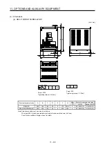
Servo amplifier
External dynamic brake
MR-J4-11KA(-RJ) DBU-11K
MR-J4-15KA(-RJ) DBU-15K
MR-J4-22KA(-RJ) DBU-22K-R1
MR-J4-11KA4(-RJ) DBU-11K-4
MR-J4-15KA4(-RJ)
MR-J4-22KA4(-RJ)
DBU-22K-4
Summary of Contents for MR-J4-100A
Page 9: ...A 8 MEMO ...
Page 61: ...1 FUNCTIONS AND CONFIGURATION 1 44 MEMO ...
Page 67: ...2 INSTALLATION 2 6 MEMO ...
Page 137: ...3 SIGNALS AND WIRING 3 70 MEMO ...
Page 261: ...6 NORMAL GAIN ADJUSTMENT 6 24 MEMO ...
Page 291: ...7 SPECIAL ADJUSTMENT FUNCTIONS 7 30 MEMO ...
Page 299: ...8 TROUBLESHOOTING 8 8 MEMO ...
Page 319: ...9 OUTLINE DRAWINGS 9 20 MEMO ...
Page 461: ...12 ABSOLUTE POSITION DETECTION SYSTEM 12 36 MEMO ...
Page 511: ...14 COMMUNICATION FUNCTION 14 38 MEMO ...
Page 559: ...16 USING A DIRECT DRIVE MOTOR 16 20 MEMO ...
Page 583: ...17 FULLY CLOSED LOOP SYSTEM 17 24 MEMO ...
Page 621: ...APPENDIX App 38 ...
Page 639: ......


