12. ABSOLUTE POSITION DETECTION SYSTEM
12 - 7
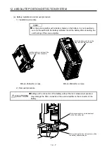
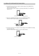
(a) Battery installation and removal procedure
1) Installation procedure
POINT
For the servo amplifier with a battery holder on the bottom, it is not possible to
wire for the earth with the battery installed. Insert the battery after executing the
earth wiring of the servo amplifier.
Install a battery, and insert the
plug into the CN4 connector.
Install a battery, and insert the
plug into the CN4 connector.
MR-J4-350A(-RJ) or less
MR-J4-500A(-RJ) or more
2) Removal procedure
CAUTION
Pulling out the connector of the battery without the lock release lever pressed
may damage the CN4 connector of the servo amplifier or the connector of the
battery.
While pressing the lock release lever,
pull out the connector.
While pressing the lock release lever, slide
the battery case toward you.
Summary of Contents for MR-J4-100A
Page 9: ...A 8 MEMO ...
Page 61: ...1 FUNCTIONS AND CONFIGURATION 1 44 MEMO ...
Page 67: ...2 INSTALLATION 2 6 MEMO ...
Page 137: ...3 SIGNALS AND WIRING 3 70 MEMO ...
Page 261: ...6 NORMAL GAIN ADJUSTMENT 6 24 MEMO ...
Page 291: ...7 SPECIAL ADJUSTMENT FUNCTIONS 7 30 MEMO ...
Page 299: ...8 TROUBLESHOOTING 8 8 MEMO ...
Page 319: ...9 OUTLINE DRAWINGS 9 20 MEMO ...
Page 461: ...12 ABSOLUTE POSITION DETECTION SYSTEM 12 36 MEMO ...
Page 511: ...14 COMMUNICATION FUNCTION 14 38 MEMO ...
Page 559: ...16 USING A DIRECT DRIVE MOTOR 16 20 MEMO ...
Page 583: ...17 FULLY CLOSED LOOP SYSTEM 17 24 MEMO ...
Page 621: ...APPENDIX App 38 ...
Page 639: ......


