12. ABSOLUTE POSITION DETECTION SYSTEM
12 - 15
12.5 Startup procedure
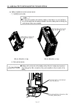
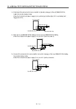
(1) Battery installation.
Refer to section 12.2.
(2) Parameter setting
Set "_ _ _ 1" in [Pr. PA03] of the servo amplifier and switch power off, then on.
(3) Resetting of [AL. 25 Absolute position erased]
After connecting the encoder cable, [AL. 25] occurs at first power-on. Turn off the power, then on to
reset the alarm.
(4) Confirmation of absolute position data transfer
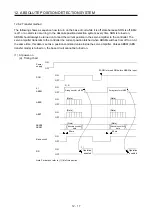
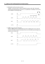
When SON is turned on, the absolute position data is transferred to the programmable controller.
Transferring the proper absolute position data will trigger the followings.
(a) RD (Ready) turns on.
(b) The absolute position data ready contact of programmable controller turns on.
(c) The MR Configurator2 ABS data display window (refer to section 12.1.5) and programmable
controller side ABS data registers show the same value (at the home position address of 0).
If any warning such as [AL. E5 ABS time-out warning] or programmable controller side transfer error
occurs, refer to section 12.7 or chapter 8 and take corrective action.
(5) Home position setting
The home position must be set if.
(a) System set-up is performed;
(b) The servo amplifier has been changed;
(c) The servo motor has been changed; or
(d) [AL. 25 Absolute position erased] occurred.
In the absolute position detection system, the absolute position coordinates are made up by making
home position setting at the time of system set-up. The motor shaft may operate unexpectedly if
positioning operation is performed without home position setting.
Always make home position setting before starting.
For the home position setting method and types, refer to section 12.6.3.
Summary of Contents for MR-J4-100A
Page 9: ...A 8 MEMO ...
Page 61: ...1 FUNCTIONS AND CONFIGURATION 1 44 MEMO ...
Page 67: ...2 INSTALLATION 2 6 MEMO ...
Page 137: ...3 SIGNALS AND WIRING 3 70 MEMO ...
Page 261: ...6 NORMAL GAIN ADJUSTMENT 6 24 MEMO ...
Page 291: ...7 SPECIAL ADJUSTMENT FUNCTIONS 7 30 MEMO ...
Page 299: ...8 TROUBLESHOOTING 8 8 MEMO ...
Page 319: ...9 OUTLINE DRAWINGS 9 20 MEMO ...
Page 461: ...12 ABSOLUTE POSITION DETECTION SYSTEM 12 36 MEMO ...
Page 511: ...14 COMMUNICATION FUNCTION 14 38 MEMO ...
Page 559: ...16 USING A DIRECT DRIVE MOTOR 16 20 MEMO ...
Page 583: ...17 FULLY CLOSED LOOP SYSTEM 17 24 MEMO ...
Page 621: ...APPENDIX App 38 ...
Page 639: ......

