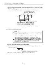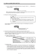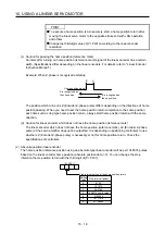
15. USING A LINEAR SERVO MOTOR
15 - 9
(4) Linear encoder resolution setting
Set the ratio of the electronic gear to the linear encoder resolution with [Pr. PL02 Linear encoder
resolution - Numerator] and [Pr. PL03 Linear encoder resolution - Denominator].
POINT
To enable the parameter values, cycle the power after setting.
(a) Parameter setting
Set the values that apply to the following equation.
[Pr. PL02 Linear encoder resolution - Numerator]
[Pr. PL03 Linear encoder resolution - Denominator]
= Linear encoder resolution [µm]
(b) Parameter setting example
When the linear encoder resolution is 0.5
μ
m
[Pr. PL02]
[Pr. PL03]
= Linear encoder resolution = 0.5 µm =
2
1
The following shows the simplified chart for the setting values of [Pr. PL02] and [Pr. PL03].
Linear encoder resolution [µm]
0.01 0.02 0.05 0.1 0.2 0.5 1.0 2.0
[Pr.
PL02] 1 1 1 1 1 1 1 2
Setting
value
[Pr.
PL03] 100 50 20 10 5 2 1 1
POINT
If an incorrect value is set for [Pr. PL02] or [Pr. PL03], the linear servo motor
may not operate properly, or [AL. 27] or [AL. 42] may occur at the positioning
operation or the magnetic pole detection.
15.3.2 Magnetic pole detection
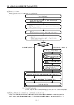
Before the positioning operation of the linear servo motor, make sure to perform the magnetic pole detection.
When [Pr. PL01] is set to the initial value, perform the magnetic pole detection only at the first servo-on after
the power is turned on.
The magnetic pole detection includes the following two methods. Each method has advantages and
disadvantages. Select a magnetic pole detection method suitable for your usage.
The position detection method is selected the initial value.
Magnetic pole detection
Advantage Disadvantage
Position detection method
1. The magnetic pole detection has a
high degree of accuracy.
2. The adjustment procedure at the
magnetic pole detection is simple.
1. The travel distance at the
magnetic pole detection is long.
2. For equipment with small friction,
the initial magnetic pole detection
error may occur.
Minute position detection method
1. The travel distance at the
magnetic pole detection is short.
2. Even for equipment with small
friction, the magnetic pole
detection is available.
1. The adjustment procedure at the
magnetic pole detection is
complex.
2. If a disturbance occurs during the
magnetic pole detection, [AL. 27
Initial magnetic pole detection
error] may occur.
Summary of Contents for MR-J4-100A
Page 9: ...A 8 MEMO ...
Page 61: ...1 FUNCTIONS AND CONFIGURATION 1 44 MEMO ...
Page 67: ...2 INSTALLATION 2 6 MEMO ...
Page 137: ...3 SIGNALS AND WIRING 3 70 MEMO ...
Page 261: ...6 NORMAL GAIN ADJUSTMENT 6 24 MEMO ...
Page 291: ...7 SPECIAL ADJUSTMENT FUNCTIONS 7 30 MEMO ...
Page 299: ...8 TROUBLESHOOTING 8 8 MEMO ...
Page 319: ...9 OUTLINE DRAWINGS 9 20 MEMO ...
Page 461: ...12 ABSOLUTE POSITION DETECTION SYSTEM 12 36 MEMO ...
Page 511: ...14 COMMUNICATION FUNCTION 14 38 MEMO ...
Page 559: ...16 USING A DIRECT DRIVE MOTOR 16 20 MEMO ...
Page 583: ...17 FULLY CLOSED LOOP SYSTEM 17 24 MEMO ...
Page 621: ...APPENDIX App 38 ...
Page 639: ......

