15. USING A LINEAR SERVO MOTOR
15 - 10
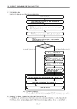
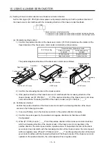
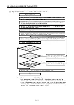
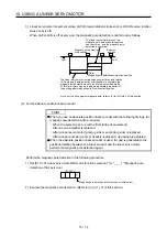
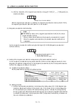
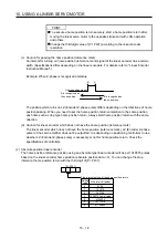
(1) Magnetic pole detection method by using MR Configurator2
The following shows the magnetic pole detection procedure by using MR Configurator2.
(a) Magnetic pole detection by the position detection method
Have [AL. 32 Overcurrent], [AL.
50 Overload 1], [AL. 51 Overload 2], and
[AL. E1 Overload warning 1]
occurred?
1) Check that LSP (Forward rotation stroke end), LSN (Reverse rotation stroke end), and EM2 (Forced
stop 2) are on, and then cycle the servo amplifier power.
Set [Pr. PL08 Linear servo motor/DD motor function selection 3] to "_ _ _ 0" to set the magnetic
pole detection method to "Position detection method".
Cycle the servo amplifier power.
5) Set [Pr. PL09 Magnetic pole detection voltage level] to "10" (guide value).
6) Execute "Positive direction travel" or "Negative direction travel" with "Positioning operation" in the
test operation mode on MR Configurator2. Set the travel distance to "0" at this time.
7) Set [Pr. PL01] to "_ _ _ 0" to set "Magnetic pole detection disabled". (Note)
2)
3)
4)
The magnetic pole detection is carried out.
Is [Pr. PL09] the final value?
Has [AL. 27 Initial magnetic pole
detection error] occurred?
Reset the alarm or cycle the
servo amplifier power.
Cycle the servo amplifier power.
Reset the alarm or cycle the
servo amplifier power.
Increase the value of [Pr. PL09]
by five.
Set an approximately 70% of the
value set for [Pr. PL09] as the
final setting value.
If [AL. 27 Initial magnetic pole
detection error] occurs with this
value, specify a value
intermediate between the value
set at [AL. E1 Overload warning
1] and the value set at [AL. 27
Initial magnetic pole detection
error] as the final setting value.
NO
YES
YES
NO
YES
NO
Magnetic pole detection
End
Set [Pr. PL01 Linear servo motor/DD motor function selection 1] to "_ _ _ 1" to enable "Magnetic
pole detection at first servo-on". (Note)
Note. For the incremental system, the [Pr. PL01] setting is not required.
Summary of Contents for MR-J4-100A
Page 9: ...A 8 MEMO ...
Page 61: ...1 FUNCTIONS AND CONFIGURATION 1 44 MEMO ...
Page 67: ...2 INSTALLATION 2 6 MEMO ...
Page 137: ...3 SIGNALS AND WIRING 3 70 MEMO ...
Page 261: ...6 NORMAL GAIN ADJUSTMENT 6 24 MEMO ...
Page 291: ...7 SPECIAL ADJUSTMENT FUNCTIONS 7 30 MEMO ...
Page 299: ...8 TROUBLESHOOTING 8 8 MEMO ...
Page 319: ...9 OUTLINE DRAWINGS 9 20 MEMO ...
Page 461: ...12 ABSOLUTE POSITION DETECTION SYSTEM 12 36 MEMO ...
Page 511: ...14 COMMUNICATION FUNCTION 14 38 MEMO ...
Page 559: ...16 USING A DIRECT DRIVE MOTOR 16 20 MEMO ...
Page 583: ...17 FULLY CLOSED LOOP SYSTEM 17 24 MEMO ...
Page 621: ...APPENDIX App 38 ...
Page 639: ......


