15. USING A LINEAR SERVO MOTOR
15 - 19
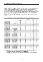
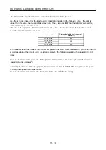
The following shows the relation between the stop interval at the home position return and the linear
encoder resolution. For example, when the linear encoder resolution is 0.001
μ
m and the parameter
for the stop interval at the home position return, [Pr.PL01], is set to "_ 5 _ _" (16777216 pulses), the
stop interval is 16.777 mm. The value inside a bold box indicates the recommended stop interval for
each linear encoder resolution.
[Unit: mm]
Linear encoder
resolution [µm]
Pr. PL01
Stop interval
[pulse]
0.001 0.005 0.01 0.02 0.05 0.1 0.2 0.5 1
2
_ 0 _ _
8192
0.008
0.041
0.082
0.164
0.410 0.819 1.638 4.096 8.192 16.384
_ 1 _ _
131072
0.131
0.655
1.311
2.621
6.554 13.107 26.214 65.536 131.072 262.144
_ 2 _ _
262144
0.262
1.311
2.621
5.243
13.107 26.214 52.429 131.072 262.144 524.288
_ 3 _ _
1048576
1.049
5.243
10.486
20.972
52.429 104.858 209.715 524.288 1048.576 2097.152
_ 4 _ _
4194304
4.194
20.972
41.943
83.886
209.715 419.430 838.861 2097.152 4194.304 8388.608
_ 5 _ _
16777216
16.777
83.886
167.772
335.544
838.861 1677.722
3355.443 8388.608 16777.216 33554.432
_ 6 _ _
67108864
67.109
335.544 671.089 1342.177 3355.443 6710.886 13421.773 33554.432 67108.864 134217.728
In the case of a proximity dog type home position return, the nearest reference home position after
proximity dog off is the home position. The linear encoder home position can be set in any position.
LZ (Encoder Z-phase pulse) is outputted based on "Stop interval selection at the home position
return" in [Pr. PL01].
Linear encoder home position
Home position
Home position return speed
Creep speed
Home position return direction
ON
OFF
Proximity dog
signal
Linear servo
motor
Reference home
position
Linear servo motor
position
0 mm/s
(Note)
1048576 pulses
1048576 pulses × n
Note. Changeable with [Pr. PL01].
POINT
The data set type home position return can also be carried out.
Summary of Contents for MR-J4-100A
Page 9: ...A 8 MEMO ...
Page 61: ...1 FUNCTIONS AND CONFIGURATION 1 44 MEMO ...
Page 67: ...2 INSTALLATION 2 6 MEMO ...
Page 137: ...3 SIGNALS AND WIRING 3 70 MEMO ...
Page 261: ...6 NORMAL GAIN ADJUSTMENT 6 24 MEMO ...
Page 291: ...7 SPECIAL ADJUSTMENT FUNCTIONS 7 30 MEMO ...
Page 299: ...8 TROUBLESHOOTING 8 8 MEMO ...
Page 319: ...9 OUTLINE DRAWINGS 9 20 MEMO ...
Page 461: ...12 ABSOLUTE POSITION DETECTION SYSTEM 12 36 MEMO ...
Page 511: ...14 COMMUNICATION FUNCTION 14 38 MEMO ...
Page 559: ...16 USING A DIRECT DRIVE MOTOR 16 20 MEMO ...
Page 583: ...17 FULLY CLOSED LOOP SYSTEM 17 24 MEMO ...
Page 621: ...APPENDIX App 38 ...
Page 639: ......

