15. USING A LINEAR SERVO MOTOR
15 - 28
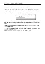
15.4.4 Permissible load to motor mass ratio when the dynamic brake is used
Use the dynamic brake under the load to motor mass ratio indicated in the following table. If the ratio is
higher than this value, the dynamic brake may burn. If there is a possibility that the ratio may exceed the
value, contact your local sales office.
The values of the permissible load to motor mass ratio in the table are the values when the linear servo
motor is used at the maximum speed.
Linear servo motor
Permissible load to motor mass ratio
[Multiplier]
LM-H3 series
40
LM-U2 series
LM-F series
100
LM-K2 series
50
When actual speed does not reach the maximum speed of the servo motor, calculate the permissible load to
motor mass ratio at the time of using the dynamic brake by the following equation. (The upper limit is 300
times.)
Permissible load to motor mass ratio of the dynamic brake = Value in the table × (Servo motor maximum
speed
2
/Actual using speed
2
)
For example, when an actual using speed is 2 m/s or less for the LM-H3P2A-07P motor (maximum speed:
3.0 m/s), the equation will be as follows.
Permissible load to motor mass ratio of dynamic brake = 40 × 3
2
/2
2
= 90 [times]
Summary of Contents for MR-J4-100A
Page 9: ...A 8 MEMO ...
Page 61: ...1 FUNCTIONS AND CONFIGURATION 1 44 MEMO ...
Page 67: ...2 INSTALLATION 2 6 MEMO ...
Page 137: ...3 SIGNALS AND WIRING 3 70 MEMO ...
Page 261: ...6 NORMAL GAIN ADJUSTMENT 6 24 MEMO ...
Page 291: ...7 SPECIAL ADJUSTMENT FUNCTIONS 7 30 MEMO ...
Page 299: ...8 TROUBLESHOOTING 8 8 MEMO ...
Page 319: ...9 OUTLINE DRAWINGS 9 20 MEMO ...
Page 461: ...12 ABSOLUTE POSITION DETECTION SYSTEM 12 36 MEMO ...
Page 511: ...14 COMMUNICATION FUNCTION 14 38 MEMO ...
Page 559: ...16 USING A DIRECT DRIVE MOTOR 16 20 MEMO ...
Page 583: ...17 FULLY CLOSED LOOP SYSTEM 17 24 MEMO ...
Page 621: ...APPENDIX App 38 ...
Page 639: ......

