17. FULLY CLOSED LOOP SYSTEM
17 - 1
17. FULLY CLOSED LOOP SYSTEM
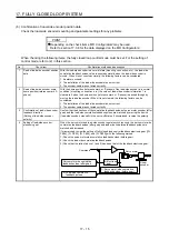
POINT
The fully closed loop system is available for the servo amplifiers of which
software version is A5 or above.
When fully closed loop control system is used with this servo amplifier, "Linear
Encoder Instruction Manual" is needed.
Fully closed loop control system is available with position control mode.
When fully closed loop control system is configured with MR-J4-_A_ servo
amplifier, the following restrictions will be applied. However, these restrictions
will not be applied for MR-J4-_A_-RJ servo amplifiers.
A/B/Z-phase differential output type encoder cannot be used.
The load-side encoder and servo motor encoder is compatible with only the
two-wire type. The four-wire type load-side encoder and servo motor encoder
cannot be used.
When you use the KG-KR and HG-MR series for driving and load-side
encoder, the optional four-wire type encoder cables (MR-EKCBL30M-L, MR-
EKCBL30M-H, MR-EKCBL40M-H, and MR-EKCBL50M-H) cannot be used.
When an encoder cable of 30 m to 50 m is needed, fabricate a two-wire type
encoder cable according to appendix 9.
17.1 Functions and configuration
17.1.1 Function block diagram
A fully closed loop control block diagram is shown below. The fully closed loop system is controlled in the
load-side encoder unit.
Servo motor-side cumulative
feedback pulses
(load-side encoder resolution unit)
(Servo motor side)
Droop pulses
(Servo motor side)
Cumulative
feedback pulses
Load-side
droop pulses
Cumulative load-side
feedback pulses
Fully closed loop
dual feedback
filter
([Pr. PE08])
(Note 2)
FBD
Servo motor
Linear encoder
Controller
(Note 1, 2)
Fully closed loop selection
([Pr. PE01] and [Pr. PE08])
+
-
FBN
S
+
-
Encoder pulse setting
([Pr. PA15], [Pr. PA16]
and [Pr. PC03])
Fully closed loop control
error detection function
selection ([Pr. PE03])
+
-
+
+
-
+
-
+
Control
Monitor
Load-side feedback pulses
CDV
CMX
Electronic gear
Note 1. Switching between semi closed loop control and fully closed loop control can be performed by changing the setting of [Pr.
PE01].
When semi closed loop control is selected, a control is always performed on the bases of the position data of the servo
motor encoder independently of whether the servo motor is at a stop or running.
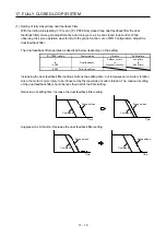
2. When the fully closed loop system is enabled in [Pr. PE01], dual feedback control in which the servo motor feedback signal
and load-side encoder feedback signal are combined by the dual feedback filter in [Pr. PE08] is performed.
In this case, fully closed loop control is performed when the servo motor is at a stop, and semi closed loop control is
performed when the servo motor is operating to improve control performance. When "4500" is set as the filter value of [Pr.
PE08 Fully closed loop dual feedback filter], fully closed loop control is always performed.
Summary of Contents for MR-J4-100A
Page 9: ...A 8 MEMO ...
Page 61: ...1 FUNCTIONS AND CONFIGURATION 1 44 MEMO ...
Page 67: ...2 INSTALLATION 2 6 MEMO ...
Page 137: ...3 SIGNALS AND WIRING 3 70 MEMO ...
Page 261: ...6 NORMAL GAIN ADJUSTMENT 6 24 MEMO ...
Page 291: ...7 SPECIAL ADJUSTMENT FUNCTIONS 7 30 MEMO ...
Page 299: ...8 TROUBLESHOOTING 8 8 MEMO ...
Page 319: ...9 OUTLINE DRAWINGS 9 20 MEMO ...
Page 461: ...12 ABSOLUTE POSITION DETECTION SYSTEM 12 36 MEMO ...
Page 511: ...14 COMMUNICATION FUNCTION 14 38 MEMO ...
Page 559: ...16 USING A DIRECT DRIVE MOTOR 16 20 MEMO ...
Page 583: ...17 FULLY CLOSED LOOP SYSTEM 17 24 MEMO ...
Page 621: ...APPENDIX App 38 ...
Page 639: ......

