APPENDIX
App. - 30
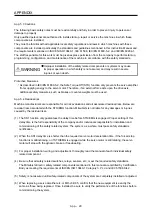
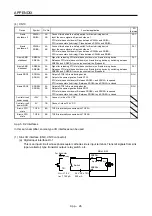
(b) Using a screwdriver
To avoid damaging housings and springs when wiring with screwdriver, do not put excessive force.
Be cautious when connecting.
1) Adjusting screw driver
Diameter: 2.3 mm ± 0.05 mm
Length: 120 mm or less
Width: 2.3 mm
Thickness: 0.25 mm
Angle in tip of the blade: 18 ± 1 degrees
2.3 mm ± 0.05 mm
0.25 mm
2.3 mm
18° ± 1°
Diameter: 2.5 mm ± 0.05 mm
Length: 120 mm or less
Width: 2.5 mm
Thickness: 0.3 mm
Angle in tip of the blade: 12 ± 1 degrees
0.3 mm
2.5 mm
12° ± 1°
2.5 mm ± 0.05 mm
Screwdriver diameter:
φ
2.3 mm
Screwdriver diameter:
φ
2.5 mm
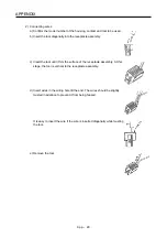
2) Connecting wires
a) Insert a screwdriver in the front slot a little diagonally, and depress the spring. While
depressing the spring, insert the wires until they hit the end. Note that the housing and spring
may be damaged if the screwdriver is inserted strongly. Never insert the screwdriver in the
wire hole. Otherwise, the connector will be damaged.
b) Pull the screwdriver out while pressing the wires. Connecting wires is completed.
c) Pull the wire lightly to confirm that the wire is surely connected.
d) To remove the wires, depress the spring by the screwdriver in the same way as connecting
wires, and then pull the wires out.
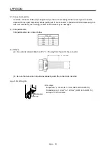
Tool insertion slot
Screw driver
Summary of Contents for MR-J4-100A
Page 9: ...A 8 MEMO ...
Page 61: ...1 FUNCTIONS AND CONFIGURATION 1 44 MEMO ...
Page 67: ...2 INSTALLATION 2 6 MEMO ...
Page 137: ...3 SIGNALS AND WIRING 3 70 MEMO ...
Page 261: ...6 NORMAL GAIN ADJUSTMENT 6 24 MEMO ...
Page 291: ...7 SPECIAL ADJUSTMENT FUNCTIONS 7 30 MEMO ...
Page 299: ...8 TROUBLESHOOTING 8 8 MEMO ...
Page 319: ...9 OUTLINE DRAWINGS 9 20 MEMO ...
Page 461: ...12 ABSOLUTE POSITION DETECTION SYSTEM 12 36 MEMO ...
Page 511: ...14 COMMUNICATION FUNCTION 14 38 MEMO ...
Page 559: ...16 USING A DIRECT DRIVE MOTOR 16 20 MEMO ...
Page 583: ...17 FULLY CLOSED LOOP SYSTEM 17 24 MEMO ...
Page 621: ...APPENDIX App 38 ...
Page 639: ......

