APPENDIX
App. - 40
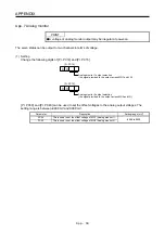
(2) Set content
POINT
When you use a linear servo motor, replace the following left words to the right
words.
(servo motor) speed
→
(linear servo motor) speed
CCW direction
→
Positive direction
CW direction
→
Negaative direction
Torque
→
Thrust
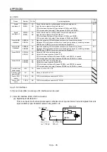
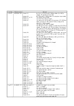
The servo amplifier is factory-set to output the servo motor speed to MO1 (Analog monitor 1) and the
torque to MO2 (Analog monitor 2). The setting can be changed as listed below by setting the [Pr. PC14]
and [Pr. PC15] value.
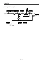
Refer to (3) for the detection point.
Setting
value
Output item
Description
Setting
value
Output item
Description
00
Servo motor speed/
Linear servo motor
speed
Maximum speed
CW direction
CCW direction
Maximum speed
0
8 [V]
-8 [V]
01 Torque/Thrust
Maximum torque
Power running in
CW direction
Power running in
CCW direction
Maximum torque
0
8 [V]
-8 [V]
02
Servo motor speed/
Linear servo motor
speed
Maximum speed
CW direction
CCW direction
Maximum speed
0
8 [V]
03 Torque/Thrust
Maximum torque
Power runningin
CW direction
Power running in
CCW direction
Maximum torque
0
8 [V]
04 Current
command
Maximum current command
(Maximum torque command)
CW direction
CCW direction
Maximum current command
(Maximum torque command)
0
8 [V]
-8 [V]
05 Command
pulse
frequency
(±10 V/±4 Mpulse/s)
4 Mpulses/s
CW direction
CCW direction
4 Mpulses/s
0
10 [V]
-10 [V]
06
Servo motor-side droop
pulses
(Note 1, 3, 5, 6)
(±10 V/100 pulses)
100 [pulse]
CW direction
CCW direction
100 [pulse]
0
10 [V]
-10 [V]
07
Servo motor-side droop
pulses
(Note 1, 3, 5, 6)
(±10 V/1000 pulses)
1000 [pulse]
CW direction
CCW direction
1000 [pulse]
0
10 [V]
-10 [V]
08
Servo motor-side droop
pulses
(Note 1, 3, 5, 6)
(±10 V/10000 pulses)
10000 [pulse]
CW direction
CCW direction
10000 [pulse]
0
10 [V]
-10 [V]
09
Servo motor-side droop
pulses
(Note 1, 3, 5, 6)
(±10 V/100000 pulses)
100000 [pulse]
CW direction
CCW direction
100000 [pulse]
0
10 [V]
-10 [V]
Summary of Contents for MR-J4-100A
Page 9: ...A 8 MEMO ...
Page 61: ...1 FUNCTIONS AND CONFIGURATION 1 44 MEMO ...
Page 67: ...2 INSTALLATION 2 6 MEMO ...
Page 137: ...3 SIGNALS AND WIRING 3 70 MEMO ...
Page 261: ...6 NORMAL GAIN ADJUSTMENT 6 24 MEMO ...
Page 291: ...7 SPECIAL ADJUSTMENT FUNCTIONS 7 30 MEMO ...
Page 299: ...8 TROUBLESHOOTING 8 8 MEMO ...
Page 319: ...9 OUTLINE DRAWINGS 9 20 MEMO ...
Page 461: ...12 ABSOLUTE POSITION DETECTION SYSTEM 12 36 MEMO ...
Page 511: ...14 COMMUNICATION FUNCTION 14 38 MEMO ...
Page 559: ...16 USING A DIRECT DRIVE MOTOR 16 20 MEMO ...
Page 583: ...17 FULLY CLOSED LOOP SYSTEM 17 24 MEMO ...
Page 621: ...APPENDIX App 38 ...
Page 639: ......

