2. INSTALLATION
2 - 4
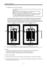
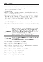
(3) When installing the cabinet in a place where toxic gas, dirt and dust exist, conduct an air purge (force
clean air into the cabinet from outside to make the internal pressure higher than the external pressure) to
prevent such materials from entering the cabinet.
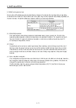
2.3 Encoder cable stress
(1) The way of clamping the cable must be fully examined so that bending stress and cable's own weight
stress are not applied to the cable connection.
(2) For use in any application where the servo motor moves, fix the cables (encoder, power supply, and
brake) with having some slack from the connector connection part of the servo motor to avoid putting
stress on the connector connection part. Use the optional encoder cable within the bending life range.
Use the power supply and brake wiring cables within the bending life of the cables.
(3) Avoid any probability that the cable sheath might be cut by sharp chips, rubbed by a machine corner or
stamped by workers or vehicles.
(4) For installation on a machine where the servo motor moves, the bending radius should be made as large
as possible. Refer to section 10.4 for the bending life.
2.4 Inspection items
WARNING
Before starting maintenance and/or inspection, turn off the power and wait for 15
minutes or more until the charge lamp turns off. Then, confirm that the voltage
between P+ and N- is safe with a voltage tester and others. Otherwise, an electric
shock may occur. In addition, when confirming whether the charge lamp is off or
not, always confirm it from the front of the servo amplifier.
To avoid an electric shock, only qualified personnel should attempt inspections.
For repair and parts replacement, contact your local sales office.
CAUTION
Do not perform insulation resistance test on the servo amplifier. Otherwise, it may
cause a malfunction.
Do not disassemble and/or repair the equipment on customer side.
It is recommended that the following points periodically be checked.
(1) Check for loose terminal block screws. Retighten any loose screws.
(2) Check the cables and the like for scratches or cracks. Inspect them periodically according to operating
conditions especially when the servo motor is movable.
(3) Check that the connector is securely connected to the servo amplifier.
(4) Check that the wires are not coming out from the connector.
(5) Check for dust accumulation on the servo amplifier.
(6) Check for unusual noise generated from the servo amplifier.
Summary of Contents for MR-J4-100A
Page 9: ...A 8 MEMO ...
Page 61: ...1 FUNCTIONS AND CONFIGURATION 1 44 MEMO ...
Page 67: ...2 INSTALLATION 2 6 MEMO ...
Page 137: ...3 SIGNALS AND WIRING 3 70 MEMO ...
Page 261: ...6 NORMAL GAIN ADJUSTMENT 6 24 MEMO ...
Page 291: ...7 SPECIAL ADJUSTMENT FUNCTIONS 7 30 MEMO ...
Page 299: ...8 TROUBLESHOOTING 8 8 MEMO ...
Page 319: ...9 OUTLINE DRAWINGS 9 20 MEMO ...
Page 461: ...12 ABSOLUTE POSITION DETECTION SYSTEM 12 36 MEMO ...
Page 511: ...14 COMMUNICATION FUNCTION 14 38 MEMO ...
Page 559: ...16 USING A DIRECT DRIVE MOTOR 16 20 MEMO ...
Page 583: ...17 FULLY CLOSED LOOP SYSTEM 17 24 MEMO ...
Page 621: ...APPENDIX App 38 ...
Page 639: ......


