


3-2
Service Adjustments
Adjustments are divided into two categories, mechani-
cal and electrical. The Electrical Adjustments are posi-
tioning (centering) adjustments and the procedures are
the same on both the LCD and DLP models.
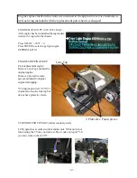
Mechanical Adjustments
The Mechanical Adjustments are similar, but differ due
to the different type Light Engines, Adjuster Assemblies
and accessing procedures differ.
The Mechanical Adjustments on the V28 chasssis are:
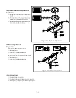
• Vertical Keystone Adjusment
• Picture Rotation Adjustmennt
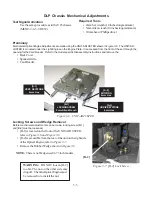
On the V29~V31 chassis the Mechanical Adjustments
are:
• Picture Rotation Adjustment
• Horizontal Keystone Adjusments
• Vertical Keystone Adjustments.
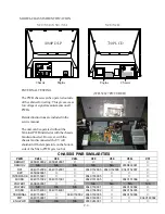
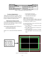
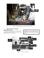
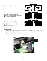
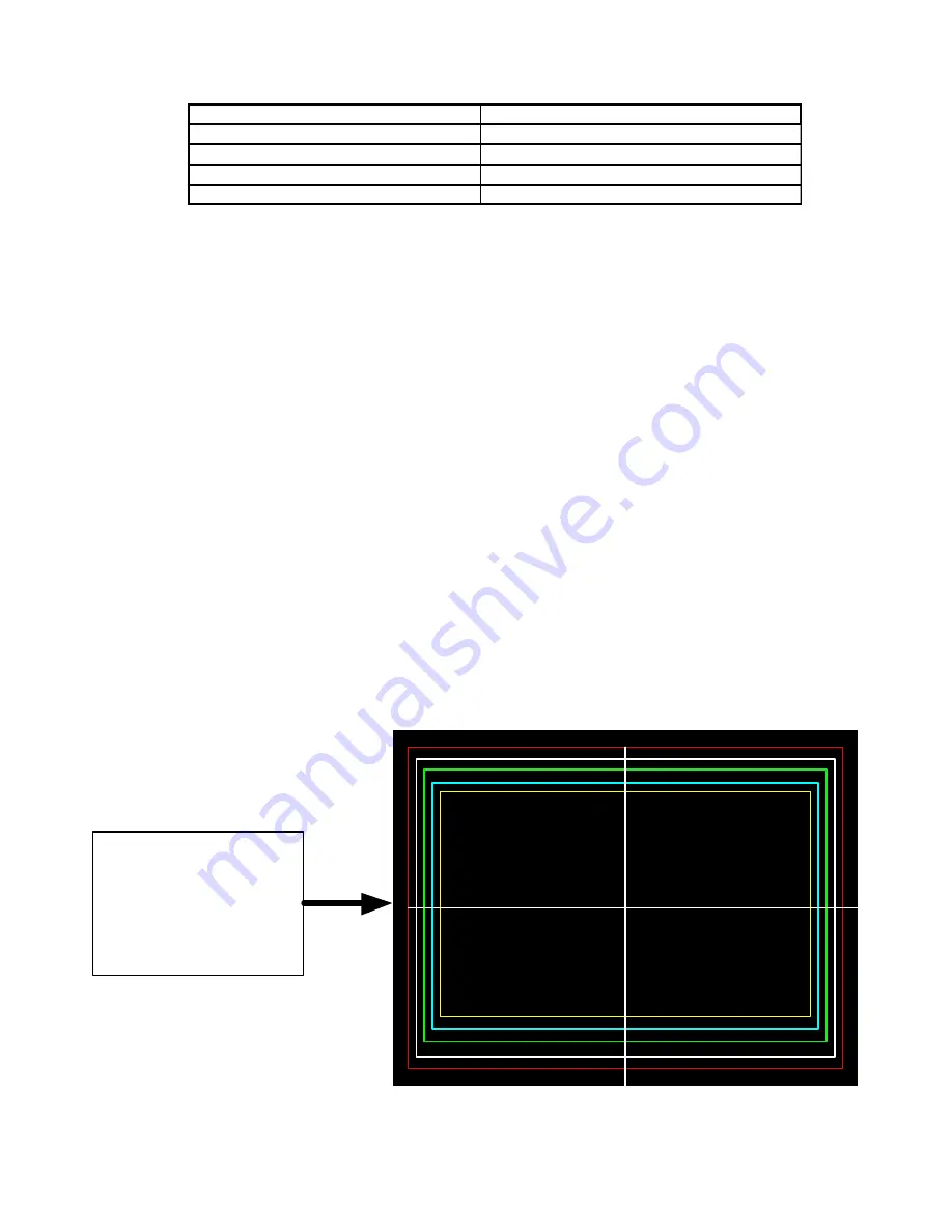
Adjustment Test Pattern
Figure 3-2
shows the internal Test Pattern is used on all
chassis to perform the adjustments. When adjustments
are complete press “MENU” twice to
The internal Test Pattern can be activated when in the
Service Adjustment Mode:
1) Press “MENU-2-4-5-7” in sequence to activate
the Service Mode.
2) Press “REW” while in the Service Mode to acti-
vate the Test pattern.
3) When Adjustments are complete press “ENTER”
to save and “MENU” twice to exit the Service
Mode.
Red = 4% overscan
White = 5% overscan
Green = 6% overscan
Cyan = 7% overscan
Yellow = 10% overscan
Figure 3-2: Internal Test Pattern
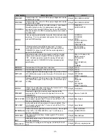
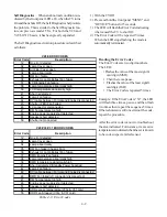
Data Transfer
MENU-2-4-5-7-0
Display
Description
Copy Engine E2PROM to DM
Transfers Engine data to DM E2PROM
Restore Backup
Restores data to factory values
UPLOAD TERMINAL BOARD DATA
DO NOT USE
Download WB Alignment to FMT
Transfers Engine data to FMT
Table 3-2: DLP Chassis Data Transfer Choices
Summary of Contents for Mr.Slim WD-52627
Page 2: ......
Page 4: ...II...
Page 50: ...4 8...
Page 54: ...5 4 Figure 5 3A V28 PWB POWER DC to DC Supplies...
Page 55: ...5 5 Figure 5 3B DLP PWB POWER DC to DC Supplies...
Page 58: ...5 8 Figure 5 7 DLP Engine Power Supply Figure 5 8 Hard Disc HDD Power Supply V30 and V31 Only...
Page 59: ...5 9 Figure 5 9...
Page 60: ...5 10 Figure 5 10...
Page 63: ...5 13 Figure 5 13 Analog Video Signal Path...
Page 64: ...5 14 Figure 5 15 Video Record Path V30 and V31 only Figure 5 14 Analog Video Signal Path...
Page 69: ...5 19 Figure 5 22 DLP Engine Protect Circuitry Figure 5 23 Short Detection Circuitry...
Page 70: ...5 20...
Page 71: ......


