
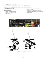
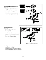
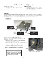
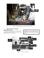


4-4
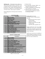
Symptom/Cause Troubleshooting
Use the following symptom/cause charts to determine
the most likely cause of a failure.
The areas covered are:
• PWB Symptom/Cause
• Optical Engine
• Power Supply PWB
• Micro & Terminal PWB
First use the PWB Symptom Cause chart to narrow
down the problem to a PWB. Then check the connec-
tions to the PWB specified. The additional charts can
help repair the set without ordering a PWB.
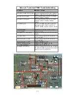
Symptom
Most Likely
Other Possibility
Video Problems, all Inputs & Menu
bad. Audio OK
Reseat DVI Cable between
Engine and Chassis
Analog Tuning problems. External
Inputs & Digital OK
PWB-DM
PWB-MICRO
Analog Tuning & External Inputs
Problems. Digital OK
PWB-MICRO
PWB-TERMINAL
Digital Tuning problems. Analog OK PWB-DM
Analog & Digital Tuning Problems.
External Inputs OK
PWB-DM
External Input Problems. Tuning OK PWB-TERMINAL PWB-MICRO
No Sync
PWB-FMT
Video Problems. Digital noise, lines
or artifacts in picture
PWB-FMT
Optical Engine
Card Reader Problems
Memory Card Reader
PWB-DM
1394 Problems
PWB-DM
Audio Problems. Speakers Bad.
Analog & Digital Out good
PWB-MICRO
Audio Problems. Speakers, Monitor
A/V 1, Audio 2, Digital Out Bad
PWB-DM
Audio Problems. Digital Good.
Analog Bad
PWB-TERMINAL
Power LED blinking constantly. Won't
power on.
PWB-DM
CableCARD problems
PWB-DM
NetCommand problems
PWB-DM
Control problems
PWB-DM
Control problems (Front Panel)
PWB-CONTROL
PWB-INTERFACE
Control problems (Remote)
PWB-PREAMP
PWB-INTERFACE
PWB Symptom/Cause Troubleshooting
Note: V28L models do not include the features below. Naturally, these models will not experience failures
associated with these features.
• TV Guide On Screen®
• CableCARD™ (
Some Versions
)
• Firewire® (IEEE1394)
• NetCommand®
• Sub-Tuner & RF Relay (Only 1 NTSC/ATSC/QAM Tuner and RF Input)
Summary of Contents for Mr.Slim WD-52627
Page 2: ......
Page 4: ...II...
Page 50: ...4 8...
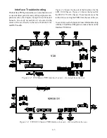
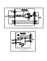
Page 54: ...5 4 Figure 5 3A V28 PWB POWER DC to DC Supplies...
Page 55: ...5 5 Figure 5 3B DLP PWB POWER DC to DC Supplies...
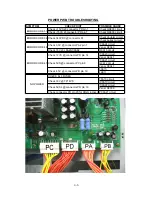
Page 58: ...5 8 Figure 5 7 DLP Engine Power Supply Figure 5 8 Hard Disc HDD Power Supply V30 and V31 Only...
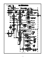
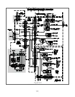
Page 59: ...5 9 Figure 5 9...
Page 60: ...5 10 Figure 5 10...
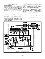
Page 63: ...5 13 Figure 5 13 Analog Video Signal Path...
Page 64: ...5 14 Figure 5 15 Video Record Path V30 and V31 only Figure 5 14 Analog Video Signal Path...
Page 69: ...5 19 Figure 5 22 DLP Engine Protect Circuitry Figure 5 23 Short Detection Circuitry...
Page 70: ...5 20...
Page 71: ......


