background image


REMOTE ENGINE STARTER 

MZ360360EX 

INSTALLATION INSTRUCTIONS 


Applicable Models 

GALANT(09.5MY-)

 ECLIPSE/SPYDER(10MY-)

 ENDEAVOR(09MY-) 


Thank you for purchasing the Mitsubishi Genuine Accessory.   

To install and use the product correctly with proper knowledge of it, read this publication carefully.   

Keep this publication for reference when maintenance is required. 


-


This publication gives precautionary instructions in the boxes titled as follows. 

Read through these instructions thoroughly. 


- Failure to follow these instructions not only prevents the product from working properly but may lead to trouble 

with the vehicle. Be sure to follow all instructions carefully. 

- If there is anything unclear about the installation, handling and/or usage of the product, contact your Mitsubishi 

Motors dealer for clarification. 

- Mitsubishi Motors Corporation is not responsible for any defects or difficulties caused by or resulting from the 

failure to follow given instructions. 

- We recommend you to have the installation performed at an authorized Mitsubishi Motors dealer. 


Caution 

 
This system is exclusively for automatic transmission vehicles. Never install this system on manual 
transmission vehicles. 

Warning 

                       Describes precautions that should be observed in order to prevent serious injury or 

death to the user. 

                       Describes precautions that should be observed in order to prevent injury or damage 

to the vehicle or its components, which may occur if sufficient care is not taken. 

                       Provides additional information that facilitates installation work. 

Note 

ZZ100-00420-0

10, 8

To the dealer: 
Be sure that the customer receives this publication

.


Attention


Warning 

Summary of Contents for MZ360360EX

Page 1: ...ng and or usage of the product contact your Mitsubishi Motors dealer for clarification Mitsubishi Motors Corporation is not responsible for any defects or difficulties caused by or resulting from the failure to follow given instructions We recommend you to have the installation performed at an authorized Mitsubishi Motors dealer Caution This system is exclusively for automatic transmission vehicle...

Page 2: ...more vehicles PRECAUTIONS Be sure to apply the parking brake securely Remove the ignition key from the key cylinder Disconnecting the cable from the battery causes the radio and audio presets the clock etc to lose their memory Record the contents of the memory before disconnecting the battery cable to allow you to reprogram the radio presets after the installation is completed Be sure to connect t...

Page 3: ...t components such as the engine and radiator Protect the harness from sharp edges by covering the edges with tape or other suitable materials Apply sealant to grommets at portions where the harness run through Do not fasten the harness to brake pipes or high pressure air conditioner pipes Fasten the additional harness to an existing vehicle harness using tape or tie wraps Bind up extra length of t...

Page 4: ...ect connection If two or more quick splice connectors are to be installed on adjacent wires do not install them side by side but stagger them to prevent interference between them If its two locks are engaged securely the quick splice connector will still perform properly even if its hinge breaks 1 If the wire of the vehicle harness to which the connector is installed is covered with vinyl tube or ...

Page 5: ...al 1 Instrument panel side cover 2 Instrument lower panel assembly 3 Steering column upper cover 4 Steering column lower cover 5 Combination meter assembly 6 Cowl side trim 7 Front pillar trim B ROUTING THE HARNESS 1 Route the harness along the vehicle harness as shown in the following two drawings Check Do not fix the harness yet It should be fixed after completing all the connecting works Cautio...

Page 6: ... 6 ...

Page 7: ... 7 ...

Page 8: ... x 70 mm 1 piece D 70 x 10 mm 1 piece 2 Wrap the two pieces of urethane sheet A around the cable of the antenna unit 3 Pass the cable of the antenna unit into the backside of the instrument panel at the bottom of the front pillar 4 Bind the antenna unit to the roof harness using the three pieces of urethane sheet B Check A A B B B B C D ...

Page 9: ...the 6 pin connector using the tie wrap 2 Apply the protective sheet over the knee absorber bracket to prevent damage to the harnesses 3 Route the harness along the instrument panel harness at the front of the deck crossmember and bundle these harnesses near the fuse holder using the tie wraps 4 Pass the 13 pin connector and the 12 pin connector of the harness over the steering shaft to the mountin...

Page 10: ...using the tie wrap 5 Bundle the excess lengths of the wires to the ground terminal and to the quick splice connector with white black wire and fix them properly on the instrument panel harness using the tie wrap 6 Connect the antenna jack of the antenna unit to the electronic control unit 7 Secure the electronic control unit and also the cable of the antenna unit on the deck crossmember stay using...

Page 11: ...the front of the ETACS ECU 2 Connect the three quick splice connectors of the harness to the wires from the gray and white 24 pin connectors connected to the ETACS ECU as follows 3 Bundle the excess lengths of the wires and fix them to the vehicle harness using the tie wraps The connector drawings show the positions of the terminals as seen from the front arrow direction of the connector Note ...

Page 12: ...the connector to the junction block 5 Disconnect the connector half on the 1 pin connector male of the harness Install the terminal drawn out in step 4 to that connector half and reconnect it to its original position 6 Fix the 1 pin connector as shown in the drawing using the tie wrap 7 Bundle the excess length of the harness leading to the 1 pin connector and fix it to the instrument panel harnes...

Page 13: ...4 Tighten the ground terminal of the harness with the instrument panel mounting nut as shown in the drawing 5 Cut the urethane sheet D to an appropriate size and fix the ground terminal wire to the instrument panel with it to prevent the wire from dangling I CHECKING AFTER INSTALLATION 1 Check that all the harnesses are connected correctly while referring to the wiring diagram 2 Check that all the...

Page 14: ...the workshop manual 2 Reprogram the radio and audio memories and adjust the clock For the reprogramming procedure refer to the owner s manual Be careful not to pinch the harnesses or damage the parts Caution Check Check The remote engine start sequence includes a minor starter run on to guarantee reliable engine starts under varying temperature conditions This condition is normal and does not harm...

Page 15: ...1 Instrument lower panel 2 Instrument panel garnish 3 Combination meter assembly 4 Instrument panel side cover 5 Steering column covers upper and lower 6 Cowl side trim 7 Front pillar trim B ROUTING THE HARNESS 1 Route the harness along the vehicle harness as shown in the following two drawings Check Do not fix the harness yet It should be fixed after completing all the connecting works Caution No...

Page 16: ... 16 ...

Page 17: ... 17 ...

Page 18: ...0 x 60 mm 1 piece D 70 x 10 mm 1 piece 2 Wrap the two pieces of urethane sheet A around the cable of the antenna unit 3 Pass the cable of the antenna unit into the backside of the instrument panel at the bottom of the front pillar 4 Bind the antenna unit to the roof harness using the three pieces of urethane sheet B Check A A B B B B C D ...

Page 19: ...et over the knee absorber bracket to prevent damage to the harnesses 3 Route the harness along the instrument panel harness at the front of the deck crossmember and fix the harnesses near the fuse holder using the tie wraps 4 Pass the 13 pin connector and the 12 pin connector of the harness over the steering shaft to the mounting position of the electronic control unit 5 Route the ground terminal ...

Page 20: ...harness along the instrument panel harness and fix the harness near the electronic control unit using the tie wrap 5 Connect the antenna jack of the antenna unit to the electronic control unit 6 Secure the electronic control unit and also the cable of the antenna unit on the deck crossmember stay using the tie wraps 7 Bundle the excess length of the antenna unit cable and fix it to the front harne...

Page 21: ...le the excess lengths of the wires and fix them to the vehicle harness using the tie wraps 3 Connect the quick splice connector with green yellow wire to the green yellow wire from the No 5 terminal of the 24 pin gray connector connected to the ETACS ECU For the quick splice connector with blue white wire its connecting point and routing differs depending on whether the vehicle is equipped with th...

Page 22: ... pin white connector connected to the ETACS ECU 5b On vehicles without theft alarm system do as follows 1 Remove the 38 pin connector of the front harness together with its mounting bracket from the vehicle 2 Connect the quick splice connector with blue white wire to the blue white wire from the No 4 terminal of the 38 pin connector 6 Bundle the excess lengths of the wires to the quick splice conn...

Page 23: ...the connector to the junction block 8 Disconnect the connector half on the 1 pin connector male of the harness Install the terminal drawn out in step 4 to that connector half and reconnect it to its original position 9 Wrap the 1 pin connector with the urethane sheet C to prevent it from rattling 10 Route the harness leading to the 1 pin connector along the instrument panel harness and secure them...

Page 24: ...amp in the engine compartment 2 Remove the front holder of the 2 pin connector Install the terminal of the sub harness for hood switch to the open cavity No 1 of the connector 3 Reinstall the front holder to the connector It clicks when it seats in position 4 Route the sub harness along the front harness and connect it to the ground point securely Refer to the workshop manual for the correct tight...

Page 25: ...nstrument panel mounting nut as shown in the drawing 4 Cut the urethane sheet D into several pieces and fix the ground terminal wire to the instrument panel with them to prevent the wire from dangling J CHECKING AFTER INSTALLATION 1 Check that all the harnesses are connected correctly while referring to the wiring diagram 2 Check that all the connectors are connected securely 3 Fix the harnesses p...

Page 26: ...the workshop manual 2 Reprogram the radio and audio memories and adjust the clock For the reprogramming procedure refer to the owner s manual Be careful not to pinch the harnesses or damage the parts Caution Check Check The remote engine start sequence includes a minor starter run on to guarantee reliable engine starts under varying temperature conditions This condition is normal and does not harm...

Page 27: ...al 1 Side cover 2 Lower panel 3 Combination meter assembly 4 Steering column upper cover 5 Steering column lower cover 6 Instrument panel under cover 7 Cowl side trim 8 Front pillar trim B ROUTING THE HARNESS 1 Route the harness along the vehicle harness as shown in the following two drawings Check Do not fix the harness yet It should be fixed after completing all the connecting works Caution Note...

Page 28: ... 28 ...

Page 29: ... 29 ...

Page 30: ...70 x 60 mm 1 piece D 70 x 10 mm 1 piece 2 Wrap the two pieces of urethane sheet A around the cable of the antenna unit 3 Pass the cable of the antenna unit into the backside of the instrument panel at the bottom of the front pillar 4 Bind the antenna unit to the roof harness using the three pieces of urethane sheet B Check A A B B B C D ...

Page 31: ... to the 6 pin connector male along the instrument panel harness and bundle the harnesses just before the connector using the tie wrap as shown in the drawing 2 Apply the protective sheet over the knee absorber bracket to prevent damage to the harness 3 Route the harness along the instrument panel harness at the front of the deck crossmember and fix the harnesses near the fuse holder using the tie ...

Page 32: ...using the tie wraps 5 Bundle the excess lengths of the wires to the ground terminal and to the quick splice connector with white black wire and fix them properly on the instrument panel harness using the tie wrap 6 Connect the antenna jack of the antenna unit to the electronic control unit 7 Secure the electronic control unit and also the cable of the antenna unit on the deck crossmember stay usin...

Page 33: ...he terminal with red green wire of the harness along the instrument panel harness toward the ETACS ECU Bundle the excess lengths of the wires and fix them to the vehicle harness using the tie wraps 3 Connect the three quick splice connectors of the harness to the wires from the gray and white 24 pin connectors connected to the ETACS ECU as follows The connector drawings show the positions of the t...

Page 34: ...stall the terminal with red green wire of the harness to that cavity Reconnect the connector to the junction block 6 Disconnect the connector half on the 1 pin connector male of the harness Install the terminal drawn out in step 4 to that connector half and reconnect it to its original position 7 Wrap the urethane tape C around the 1 pin connector to prevent rattling 8 Fix the 1 pin connector harn...

Page 35: ...nting nut as shown in the drawing 4 Cut the urethane sheet D into several pieces and fix the ground terminal wire to the instrument panel with them to prevent the wire from dangling I CHECKING AFTER INSTALLATION 1 Check that all the harnesses are connected correctly while referring to the wiring diagram 2 Check that all the connectors are connected securely and the harnesses are routed properly 3 ...

Page 36: ...he workshop manual 2 Reprogram the radio and audio memories and adjust the clock For the reprogramming procedure refer to the owner s handbook Be careful not to pinch the harnesses or damage the parts Caution Check Check The remote engine start sequence includes a minor starter run on to guarantee reliable engine starts under varying temperature conditions This condition is normal and does not har...

Page 37: ...tch Lock Mark lights when the switch of the remote controller is pushed Replace the battery for the new article referring to the owner s manual if the Battery Mark lights when the switch of the remote controller is pushed Beep Never perform the registration and operation check procedures simultaneously on some vehicles to prevent duplicated registration Caution The remote controller should be chec...

Page 38: ...will beep three times In such case retry the registration procedure from the beginning The step that has a time limit is shown by a black arrow The remote controller will not be registered if the procedure is not performed in the correct way In such case disconnect the terminal of the vehicle s battery once and then retry the registration procedure from the beginning Caution 1 Set the vehicle in t...

Page 39: ...y from LOCK OFF to ACC to LOCK OFF When the key is returned to the LOCK OFF position the buzzer of the ECU will beep once Then remove the ignition key 5 Perform the engine stop operation by the remote controller If the remote controller is operated correctly the buzzer of the ECU will beep twice NG If any switch except the engine stop switch is pushed in the above step 5 the registration operation...

Page 40: ... OK NG OK Check The engine starts Perform the engine start operation 3 Check the hazard answer back function Are hazard warning lamps flash once when the engine is starting Are the hazard warning lamps flash three times if the engine start operation is performed while the engine is starting OK Check On ENDEAVOR models make sure to set the interior light switch to ROOM position before proceeding Ca...

Page 41: ...pen the hood and perform the engine start operation The engine would not start NG Go to Troubleshooting C Perform the engine start operation with a door opened The engine would not start OK Close all doors insert the ignition key into the key cylinder and perform the engine start operation The engine would not start ...

Page 42: ... 42 Circuit Diagram ...

Page 43: ... 43 ...

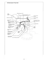
Page 44: ... 44 Troubleshooting P 38 step 2 ...

Page 45: ... 45 P 38 step 2 3 ...

Page 46: ... 46 P 41 step 3 3 ...

Page 47: ... 47 P 51 terminal No 3 P 51 ...

Page 48: ... 48 P 51 P 51 terminal No 13 ...

Page 49: ... 49 P 51 terminal No 24 P 51 terminal No 18 ...

Page 50: ... 50 ...

Page 51: ... to 14 V F 6 Voltage between the terminal and the body ground Ignition key position OFF ACC 0 V 10 to 14 V F 8 Continuity between the terminal and the body ground Hazard warning lamp switch OFF ON No continuity Continuity exists G 10 Continuity between the terminal and the body ground Insert the ignition key into the key cylinder Remove the key No continuity Continuity exists G 11 Continuity betwe...

Reviews: