11
4.1 Overcurrent-Trip Characteristics (Delay
Tripping)
Tripping times for overcurrents of 130 and 200% of
rated current are given in Table 4.1, assuming ambi-
ent temperatures of 40
°
C, a typical condition inside
of panelboards. The figures reflect all poles tested to-
gether for 130% tripping, and 105% non-tripping.
Within the range of the long-delay-element (thermal
or hydraulic) operation, tripping times are substan-
tially linear, in inverse relationship to overcurrent mag-
nitude.
The tripping times are established to prevent ex-
cessive conductor-temperature rise; although times
may vary among MCCBs of different makers, the lower
limit is restricted by the demands of typical loads: tung-
sten-lamp inrush, starting motor, mercury-arc lamps,
etc. The tripping characteristics of Mitsubishi MCCBs
are established to best ensure protection against ab-
normal currents, while avoiding nuisance tripping.
4.1.1 Ambient Temperature and Thermal Tripping
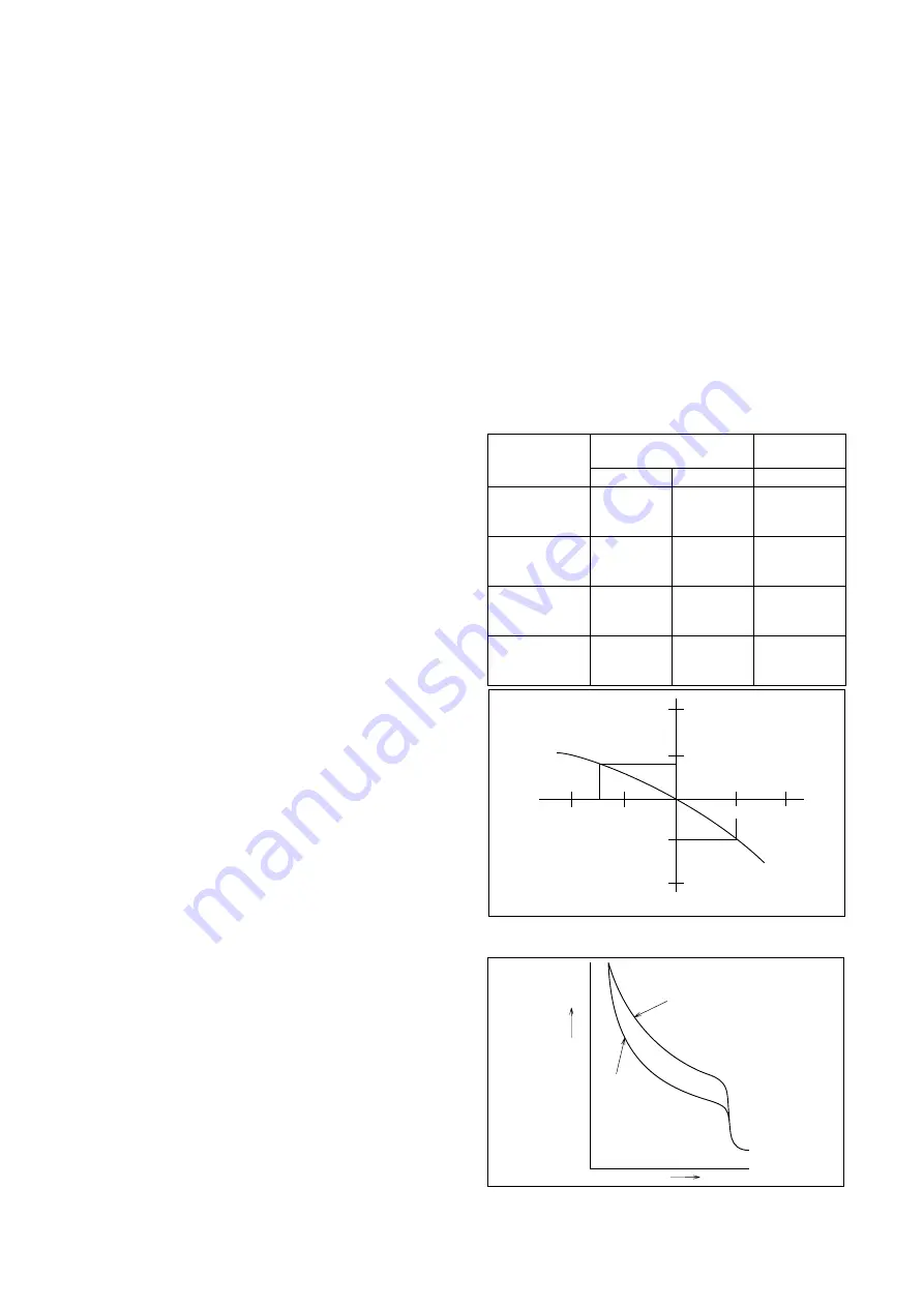
Fig. 4.1 is a typical ambient compensation curve
(curves differ according to types and ratings), show-
ing that an MCCB rated for 40
°
C ambient use must
be derated to 90% if used in a 50
°
C environment. In
an overcurrent condition, for the specified tripping time,
tripping would occur at 180% rated current, not 200%.
At 25
°
C, for the same tripping time, tripping would
occur at 216%, not 200%.
4.1.2 Hot-State Tripping
The tripping characteristics described above reflect
“cold-state tripping” – i.e., overloads increased from
zero – and the MCCB stabilized at rated ambient. This
is a practical parameter for most uses, but in intermit-
tent operations, such as resistance welding, motor
pulsing, etc., the “hot state” tripping characteristic must
be specified, since over-loads are most likely to oc-
cur with the MCCB in a heated state, while a certain
load current is already flowing.
Where the MCCB is assumed to be at 50% of rat-
ing when the overload occurs, the parameter is called
the 50% hot-state characteristic; if no percentage is
specified, 100% is assumed. Hot-state ratings of 50%
and 75% are common.
4.2 Short-Circuit Trip Characteristics (In-
stantaneous Tripping)
For Mitsubishi MCCBs with thermal-magnetic trip units
the instantaneous-trip current can be specified inde-
pendently of the delay characteristic, and in many
cases this parameter is adjustable offering consider-
able advantage in coordination with other protection
and control devices. For example, in coordination with
motor starters, it is important to set the MCCB instan-
taneous-trip element at a lower value than the fusing
(destruction) current of the thermal overload relay
(OLR) of the starter.
For selective tripping, it must be remembered that
even though the branch-MCCB tripping time may be
shorter than the total tripping time of the main MCCB,
in a fault condition the latter may also be tripped be-
cause its latching curve overlaps the tripping curve of
the former. The necessary data for establishing the
required compatibility is provided in the Mitsubishi
MCCB sales catalogues.
The total clearing time for the “instantaneous” trip-
ping feature is shown in Fig. 4.3; actual values differ
for each MCCB type.
Table 4.1 Overcurrent Tripping Times
Rated current
(A)
30 or less
31~63
64~100
101~250
251~400
401~630
631~800
801~1000
1001~1250
1251~1600
1601~2000
2001~4000
Tripping time
(minutes, max.)
200%
8.5
4
8.5
8
10
12
14
16
18
20
22
24
130%
60
60
120
120
120
120
120
120
120
120
120
120
120
120
120
120
120
120
120
120
120
60
60
120
105%
Non-Tripping time
(minutes, max.)
20
25
Ambient temperature (
:
)
% rating compensation
30
40
110
108
100
50
60
90
80
120
Fig. 4.1 Typical Temperature-Compensation Curve
Cold state
Operating time
Current
Hot state
Fig. 4.2 Hot-State-Tripping Curve
4. CHARACTERISTICS AND PERFORMANCE


