61
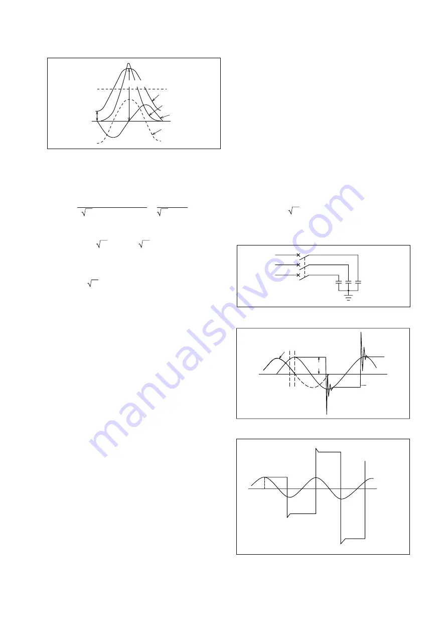
Core saturation
flux
φ
r
P
Normal flux
Transient flux
Surge current
Voltage
2
φ
m
+
φ
R
Fig. 7.7 Excitation Surge Effects
In MC CB selection for 400V, 50kVA transformer-
primary used, rated RMS current is:
3 x Voltage (V)
Capacity (kVA) x 10
3
I
=
= 72.2A
3 x 400
50 x 10
3
=
From Table 7.2, the peak value of the excitation surge
current
I
φ
is 23 times that of the rated current, hence:
I
φ
=23 x 2
I
= 23 x 2 x 72.2A = 2348A
Thus the MCCB selected should have instantaneous
trip current of no less than 2348A. The Type NF250-
SP 150A MCCB, with:
I
inst
= 2 x 150 x 11.2 = 2376A
satisfies the above condition. Thus the 3-pole version
of this type is suitable for this application.
Examples of MCCBs selected in this way are shown
in Table 7.3; it is necessary to confirm that the short-
circuit capacities of the breakers given are adequate
for the possible primary-side short-circuit current in
each case.
7.6 MCCBs for Use in Capacitor (PF Cor-
rection) Circuits
The major surge tendency results from circuit open-
ing due to the leading current. If the capacitor circuit
of Fig. 7.8 is opened at time t
1
in Fig. 7.8, arc extinc-
tion will occur at time t
2
, the zero-point of the leading
current (i). Subsequently the supply-side voltage (V
t
)
will vary normally, but the load-side voltage (V
c
) will
be maintained at the capacitor charge value. The po-
tential difference (V
c
-V
t
) will appear across the MCCB
contacts and at time t
3
, approximately 1/2-cycle after
t
2
, will become about twice the peak value of the sup-
ply voltage (E
m
). If the MCCB contacts are not suffi-
ciently open, an arc will reappear across the gap, re-
sulting in an oscillatory capacitor discharge (at a fre-
quency determined by the circuit reactance, includ-
ing the capacitor) to an initial peak-to-peak amplitude
of 4E
m
. When the arc extinguishes, V
c
will once again
be maintained at a potential of –E
m
and the potential
difference across the MCCB contacts will increase
again. This cycle will repeat until the gap between the
contacts becomes too great, and the interruption will
be completed.
Since Mitsubishi MCCBs exhibit extremely rapid
contact separation, repetitive arcing is virtually non-
existent; however, some MCCBs do not make and
break so rapidly, and in such cases, if the load ca-
pacitance is large enough, they will not discharge
quickly, and if the arc extinguishes near the peak of
the reverse-going oscillation voltage, the capacitor
voltage will be maintained in the region of –3E
m
by
the first restriking of the arc; at the second restrike it
will become 5E
m
, on the third –7E
m
, etc., ultimately
leading to breakdown of the capacitor. Thus, rapid
switching is essential in leading power-factor circuits.
In selecting an MCCB, first consider the surge cur-
rent. If the supply voltage is V volts, the capacitor C
farads, the frequency f Hertz and the current
Ι
amp,
the kVA rating (P) becomes:
For a three-phase system:
1000 P = 3 V
I
= 2
π
fCV
2
For a single-phase system:
1000 P = V
I
= 2
π
fCV
2
V
t
V
c
C
Fig. 7.8 Capacitor Circuit
V
t
V
c
V
c
i
V
c
t
1
t
2
t
3
E
m
E
m
Fig. 7.9 Circuit-Opening Conditions
V
c
= –3Em
V
t
V
c
= Em
V
c
= –7E
m
V
c
= 5E
m
Circuit
opening
Fig. 7.10 Accumulative Capacitor Charge
When the switch (Fig. 7.11) is closed, a charge
(q=CV) must be instantaneously supplied to equal the


