8
■
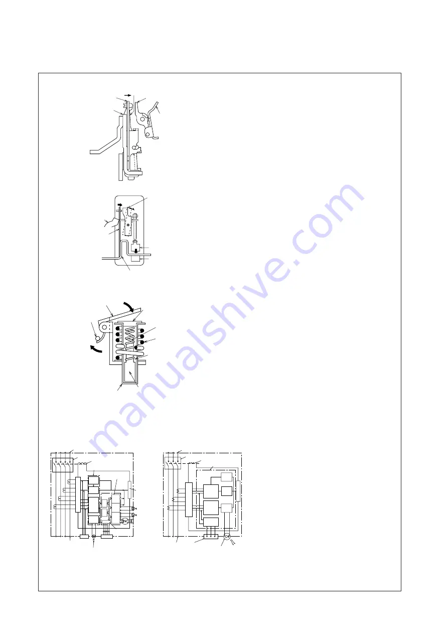
Automatic Tripping Devices
●
Thermal-Magnetic Type (100~630A Frame)
1. Time-Delay Operation
An overcurrent heats and warps the bi-
metal to actuate the trip bar.
2. Instantaneous Operation
If the overcurrent is excessive, the
amature is attracted and the trip bar ac-
tuated.
Fig. 3.3
●
Thermal-Magnetic Type (1000~4000A Frame)
1. Time-Delay Operation
An overcurrent heats and warps the bi-
metal to actuate the trip bar.
2. Instantaneous Operation
If the overcurrent is excessive, magneti-
zation of the stationary core is strong
enough to attract the armature and ac-
tuate the trip bar.
Fig. 3.4
●
Hydraulic-Magnetic Type (30~60A Frame)
1. Time-Delay Operation
At an overcurrent flow, the magnetic
force of the coil overcomes the spring,
the core closes to the pole piece, attracts
the armature, and actuates the trip bar.
The delay is obtained by the viscosity of
silicon oil.
2. Instantaneous Operation
If the overcurrent is excessive, the ar-
mature is instantly attracted, without the
influence of the moving core.
Fig. 3.5
●
Principle of Electronic Trip Relay (ETR) Operation
1. The current flowing in each phase is
monitored by a current transformer (CT).
2. Each phase of the transformed current
undergoes full-phase rectification in the
rectifier circuit.
3. After rectification, each of the currents
are converted by a peak-conversion and
an effective-value conversion circuit.
4. The largest phase is selected from the
converted currents.
5. Each time-delay circuit generates a time
delay corresponding to the largest
phase.
6. The trigger circuit outputs a trigger sig-
nal.
7. The trip coil is excited, operating the
switching mechanism.
Fig. 3.6
Armature
Trip bar
Silicon oil
Moving core
Damping spring
Pipe
Coil
Pole piece
Bimetal
Heater
Armature
Trip bar
Latch
Bimetal
Latch
Heater
Stationary core
Armature
Trip bar
Power-source side terminal
Load-side
terminal
Breaking mechanism
Rectifying circuit
Test input
Load-current indication LED (70%)
Trip coil
Custom
I
C
I
CV
PSS
WDT
Microcomputer
CPU
Characteristics
setting part
A/D
convertor
SSW
LSW
PSW
Input and
output
Trigger circuit
Trigger circuit
Over-current
indication LED
Pre-alarm
indication LED
Pre-alarm
output
CT
CT
CT
CT
CT
CT
CT
Power-supply side terminal
Load-side
terminal
Test
terminals Overcurrent display
LED
(1000~1600A Frame)
(100~800A Frame)
Switching mechanism
Trip coil
Peak
conversion
and
largest-phase
selection
Effective value
conversion
and
largest-phase
selection
Test-signal
generator
circuit
Long-
delay
circuit
Short-
delay
circuit
Instan-
taneous
circuit
Special
I
C
Rectifier circuit


