13
Your company internal use only.
Copyright (C) Mitsubishi Electric Corporation.
NR-242UM-13LND0,13-WS
DISASSEMBLING PROCEDURES
●
Disassembling procedures
In reverse of assembling procedures.
●
Assembling procedures
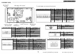
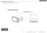
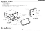
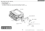
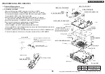
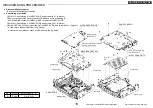
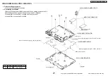
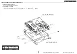
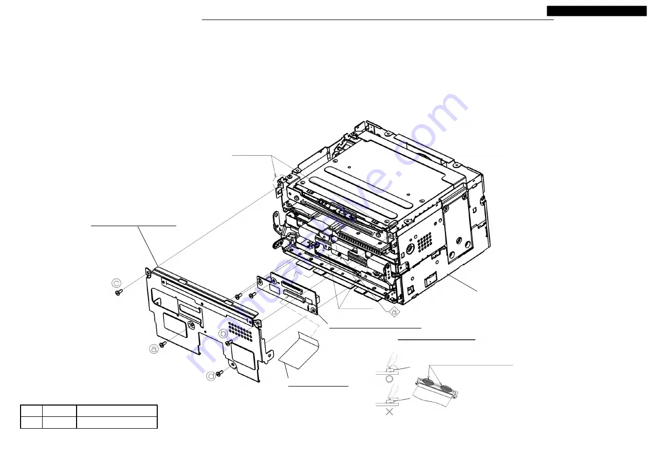
1.Screw S3-CHASSIS and M058 with
Ⓐ
(2 places), after remove the back connector cap of M058
and set it to positioning A of S3-CHASSIS and insert M058 BtoB connectors.
Insert the FPC(a) of S3-CHASSIS to the connector of M058, and lock.
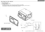
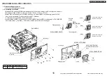
2.Insert the M001 to the connector of M058, and lock.
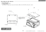
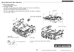
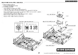
3.Set M044 to positioning B and screw with
Ⓐ
. (4 places)
<Turn to tighten a screw> Tighten a screw in order of
ⓐ
→
ⓑ
→
ⓒ
→
ⓓ
.
S3-CHASSIS
M001: FPC-MONI
M044: ASSY-CHASSIS-F
No.
Screw Tighten torque(N
・
m
)
Ⓐ
2.6X6
0.4 +0.2/-0.1
Detail of M058
Positioning A
Ⓐ
x 2
Ⓐ
x 4
Positioning B
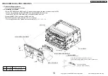
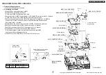
Press the neighborhood of both ends of the lock.
There is fear of being warped in the lock center neighborhood.
Locke press direction
(press it in rotatory direction)
M058: ASSY-PCB-BRIDGE


