18
Your company internal use only.
Copyright (C) Mitsubishi Electric Corporation.
NR-242UM-13LND0,13-WS
DISASSEMBLING PROCEDURES
●
Disassembling procedures
In reverse of assembling procedures.
●
Assembling procedures
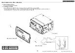
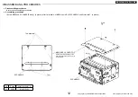
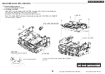
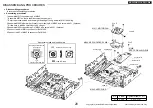
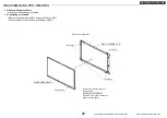
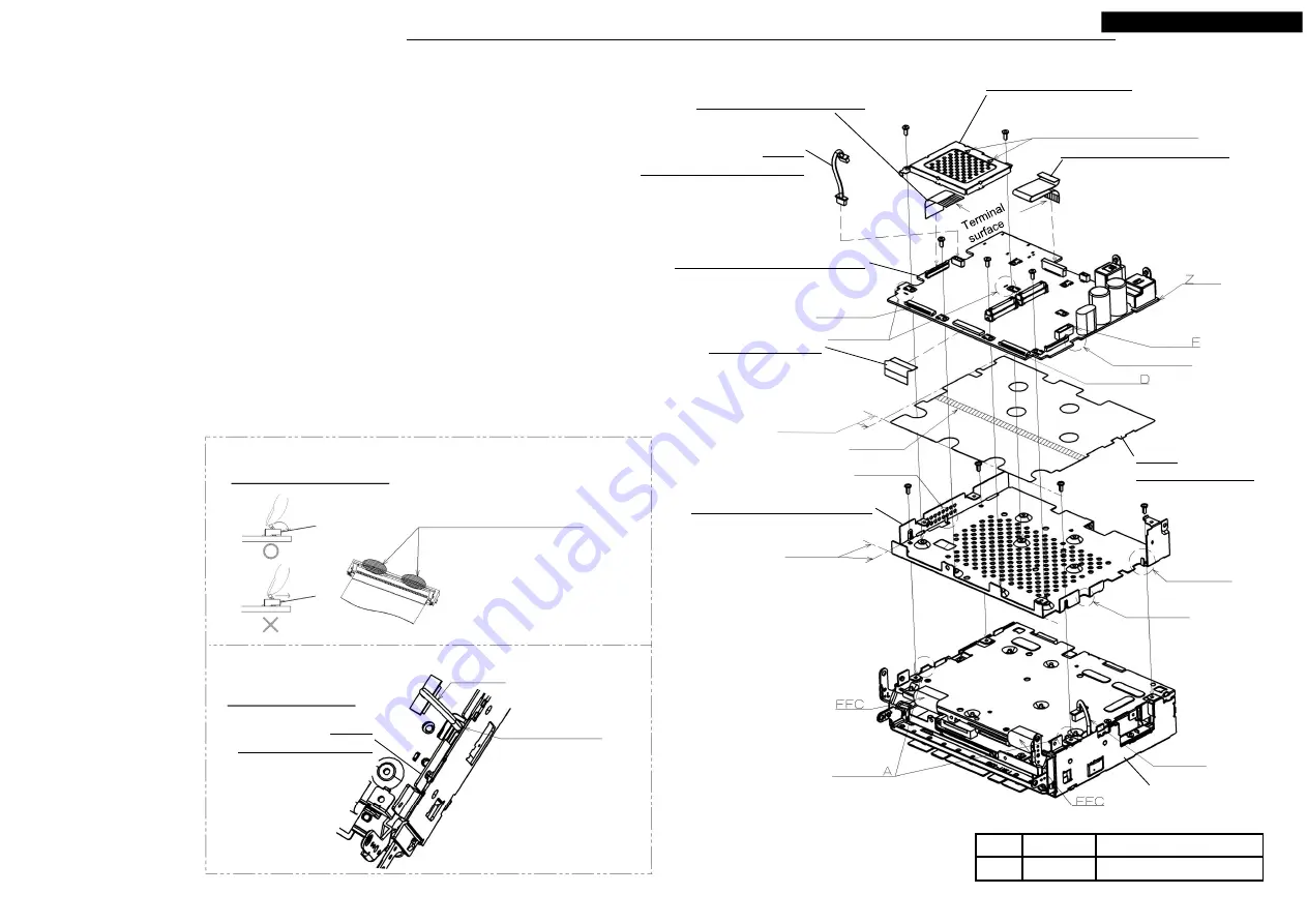
1.Remove the separator of M027 and stick it on a fit norm of M014.
2.Set M014 in positioning A of S5-CHASSIS, and screw with
Ⓐ
. (4 places)
At that time, let through a lead of S5-CHASSIS to the notch point(1) of M014.
* Do not transform M014 at the time of assembling.
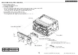
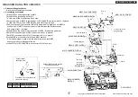
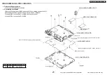
3.Set M056 from the Z side to positioning B and screw with
Ⓐ
. (3 places)
* Put the lead of S5-CHASSIS at the position of the notch point(2) and set it.
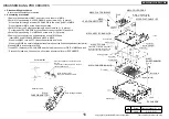
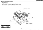
4.Set M024 in positioning C of M056 and screw with
Ⓐ
. (2 places)
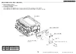
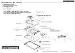
5.Remove the connector cap and adsorption sheet of M056 and
insert M009 and M008 and M006 and M002 in M056.
When lock M002, turn an FFC fixation department, and lock it.
* When lock M002, be careful about the transformation of the fixation department (reel parts).
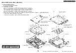
6.Insert M009 in a connector of M056.
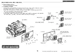
7.Insert FFC (2 pieces) of S5-CHASSIS and the lead in a connector D/E/F of M056 and lock.
* Process the lead, and it does not swell out than an external form of S5-CHASSIS.
Fit norm
Positioning B
Separator
The bottom of the terminal surface.
Insert the side with the mark of "A"
in a connector. * Do not bend it.
M002: FPC-ANA
Pasting position
Connector E
Positioning C
Connector
side
Positioning B
Notch point(1)
Notch point(2)
Positioning
Lead
Match a
△
mark with the
connector side of the set.
Ⓐ
x 2
Ⓐ
x 4
Connector
M009:
LEAD-CONNECTOR 5P
M006: FLAT-CABLE 40P
M024: COVER-DDR2
Lead
Hole through the lead
Detail of Lead
Press the neighborhood of both ends of
the lock.
There is fear of being warped in the lock
center neighborhood.
Locke press direction
(press it in rotatory direction)
Detail of M002
M027:
SHEET-ANALOG
M014: CHASSIS-ANALOG
No.
Screw
Tighten torque(N
・m)
Ⓐ
2.6X6
0.4 +0.2/-0.1
S5-CHASSIS
M056: ASSY-PCB-ANALOG
M008: FLAT-CABLE 18P
M014:
CHASSIS-ANALOG
Ⓐ
x 3
Terminal
surface

