GENERAL ±
How to Use Troubleshooting/Inspection Service Points
00-11
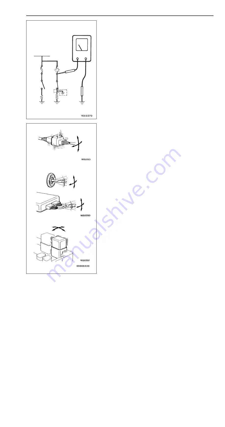
INSPECTION SERVICE POINTS FOR A BLOWN
FUSE
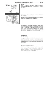
Remove the fuse and measure the resistance between the
load side of the fuse and the earth. Set the switches of all
circuits which are connected to this fuse to a condition of
continuity. If the resistance is almost 0
Ω
at this time, there
is a short somewhere between these switches and the load.
If the resistance is not 0
Ω
, there is no short at the present
time, but a momentary short has probably caused the fuse
to blow.
The main causes of a short circuit are the following.
Harness being clamped by the vehicle body
Damage to the outer casing of the harness due to wear
or heat
Water getting into the connector or circuitry
Human error (mistakenly shorting a circuit, etc.)
POINTS TO NOTE FOR INTERMITTENT
MALFUNCTIONS
Intermittent malfunctions often occur under certain conditions,
and if these conditions can be ascertained, determining the
cause becomes simple. In order to ascertain the conditions
under which an intermittent malfunction occurs, first ask the
customer for details about the driving conditions, weather
conditions, frequency of occurrence and trouble symptoms,
and then try to recreate the trouble symptoms. Next, ascertain
whether the reason why the trouble symptom occurred under
these conditions is due to vibration, temperature or some other
factor. If vibration is thought to be the cause, carry out the
following checks with the connectors and components to
confirm whether the trouble symptom occurs.
The objects to be checked are connectors and components
which are indicated by inspection procedures or given as
probable causes (which generates diagnosis codes or trouble
symptoms.)
Gently shake the connector up, down and to the left and
right.
Gently shake the wiring harness up, down and to the
left and right.
Gently rock each sensor and relay, etc. by hand.
Gently shake the wiring harness at suspensions and other
moving parts.
NOTE
If determining the cause is difficult, the flight recorder function
of the MUT-
II
can also be used.
Battery
Fuse
Load
switc
h
Load
Connector
inspection
0
Ω
Summary of Contents for Pajero Pinin 1999
Page 32: ...NOTES ...
Page 73: ...13A 1 FUEL CONTENTS GASOLINE DIRECT INJECTION GDI 13A FUEL SUPPLY 13B ...
Page 190: ...NOTES ...
Page 191: ...13B 1 FUEL SUPPLY CONTENTS FUEL TANK 2 Fuel Pump Module 4 ...
Page 214: ...NOTES ...
Page 222: ...NOTES ...
Page 256: ...NOTES ...
Page 274: ...NOTES ...
Page 282: ...NOTES ...
Page 360: ...NOTES ...
Page 412: ...NOTES ...
Page 443: ...32 1 POWER PLANT MOUNT CONTENTS ENGINE MOUNTING 2 TRANSMISSION MOUNTING 3 ...
Page 446: ...NOTES ...
Page 447: ......
Page 448: ......
Page 449: ......
Page 450: ......
Page 451: ......
Page 452: ......
Page 453: ......
Page 454: ......
Page 455: ......
Page 456: ......
Page 457: ......
Page 458: ......
Page 459: ......
Page 460: ......
Page 461: ......
Page 467: ...NOTES ...
Page 468: ...BASIC BRAKE SYSTEM 35A ANTI SKID BRAKING SYSTEM ABS 4WD 35B 35A 1 SERVICE BRAKES CONTENTS ...
Page 499: ...NOTES ...
Page 531: ...NOTES ...
Page 541: ...NOTES ...
Page 649: ...NOTES ...
Page 728: ...54A 1 CHASSIS ELECTRICAL CONTENTS CHASSIS ELECTRICAL 54A SMART WIRING SYSTEM SWS 54B ...
Page 883: ...NOTES ...
Page 919: ...NOTES ...


