GDI ±
Fuel Pump (High Pressure) and Fuel Pressure Regulator (High Pressure)
13A-109
Fuel pump (High pressure) removal
steps
"
F
A D
Fuel pump (high pressure) air bleeding
D
Throttle body removal (Refer to
P.13A-113.)
A
A
"
1. Fuel pump protector
"
C
A
2. Fuel feed pipe
"
B
A
3. Back-up ring A
"
B
A
4. O-ring
"
B
A
5. Back-up ring B
6. Fuel pressure hose clamp
"
C
A
7. Fuel pressure hose connection
8. O-ring
9. Fuel return hose connection
"
E
A
10. Fuel pump (high pressure)
11. O-ring
12. Fuel pump return nipple
13. O-ring
Fuel pressure regulator (High
pressure) removal steps
D
Intake manifold assembly removal
(Refer to GROUP 15.)
14. Fuel pressure sensor connector
connection
15. Fuel pressure sensor
"
D
A
16. O-ring
"
D
A
17. Back-up ring
"
C
A
18. Fuel return pipe
"
B
A
19. Back-up ring A
"
B
A
20. O-ring
"
B
A
21. Back-up ring B
22. Fuel return hose connection
"
A
A
23. Fuel pressure regulator (high
pressure)
24. Spacer
25. Fuel nipple
26. O-ring
REMOVAL SERVICE POINT
A
A
"
FUEL PUMP PROTECTOR REMOVAL
Lift up the transmission with a jack to create clearance between
the engine and front deck, and then remove the fuel pump
protector.
INSTALLATION SERVICE POINTS
"
A
A
FUEL PRESSURE REGULATOR (HIGH
PRESSURE) INSTALLATION
1.
Install provisionally the fuel pressure regulator (high
pressure) to the spacer.
2.
Install the fuel return pipe, and then tighten the fuel pressure
regulator (high pressure) to the specified torque.
"
B
A
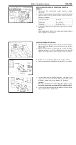
BACK-UP RING B/O-RING/BACK-UP RING A
INSTALLATION
Install the back-up rings and the O-ring as shown in the
illustration.
Caution
1.
Install the back-up ring B facing its cutaway surface
toward the opposite side of the O-ring as shown in
the illustration.
2.
Confirm the outer diameter of the back-up ring A. Take
care not to install the back-up ring for the fuel pressure
sensor by mistake. (Outer diameter of the back-up
ring A: 14.8 mm)
Cutaway
surface
Back-up ring A
O-ring
Back-up ring B
Summary of Contents for Pajero Pinin 1999
Page 32: ...NOTES ...
Page 73: ...13A 1 FUEL CONTENTS GASOLINE DIRECT INJECTION GDI 13A FUEL SUPPLY 13B ...
Page 190: ...NOTES ...
Page 191: ...13B 1 FUEL SUPPLY CONTENTS FUEL TANK 2 Fuel Pump Module 4 ...
Page 214: ...NOTES ...
Page 222: ...NOTES ...
Page 256: ...NOTES ...
Page 274: ...NOTES ...
Page 282: ...NOTES ...
Page 360: ...NOTES ...
Page 412: ...NOTES ...
Page 443: ...32 1 POWER PLANT MOUNT CONTENTS ENGINE MOUNTING 2 TRANSMISSION MOUNTING 3 ...
Page 446: ...NOTES ...
Page 447: ......
Page 448: ......
Page 449: ......
Page 450: ......
Page 451: ......
Page 452: ......
Page 453: ......
Page 454: ......
Page 455: ......
Page 456: ......
Page 457: ......
Page 458: ......
Page 459: ......
Page 460: ......
Page 461: ......
Page 467: ...NOTES ...
Page 468: ...BASIC BRAKE SYSTEM 35A ANTI SKID BRAKING SYSTEM ABS 4WD 35B 35A 1 SERVICE BRAKES CONTENTS ...
Page 499: ...NOTES ...
Page 531: ...NOTES ...
Page 541: ...NOTES ...
Page 649: ...NOTES ...
Page 728: ...54A 1 CHASSIS ELECTRICAL CONTENTS CHASSIS ELECTRICAL 54A SMART WIRING SYSTEM SWS 54B ...
Page 883: ...NOTES ...
Page 919: ...NOTES ...

