ABS <4WD> ±
G Sensor
35B-31
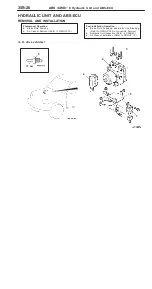
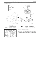
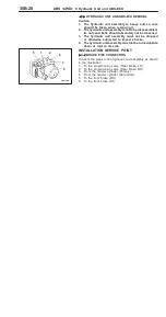
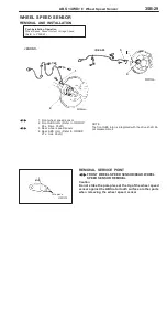
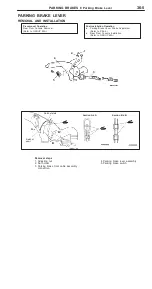
G SENSOR
REMOVAL AND INSTALLATION
Caution
Do not drop the G sensor or subject it to any shocks.
Pre-removal and Post-installation Operation
Rear floor console removal and installation
(Refer to Group 52A.)
5 Nm
G sensor
INSPECTION
1.
Remove the G sensor.
2.
Connect the special tool between the disconnected
connectors, and then place the G sensor horizontally as
shown in the illustration.
3.
Turn on the ignition switch, and then measure the voltage
between terminal No.2 and body earth.
Standard value: 2.4 ± 2.6 V
4.
Face the labeled surface straight down with the special
tool still connected. Measure the voltage between terminal
No.2 and body earth with the labeled surface faced straight
down.
Standard value: 3.3 ± 3.7 V
5.
If not within the standard value, check the power supply
line and earth condition, and then replace the G sensor.
MB991348
Label
Label
Summary of Contents for Pajero Pinin 1999
Page 32: ...NOTES ...
Page 73: ...13A 1 FUEL CONTENTS GASOLINE DIRECT INJECTION GDI 13A FUEL SUPPLY 13B ...
Page 190: ...NOTES ...
Page 191: ...13B 1 FUEL SUPPLY CONTENTS FUEL TANK 2 Fuel Pump Module 4 ...
Page 214: ...NOTES ...
Page 222: ...NOTES ...
Page 256: ...NOTES ...
Page 274: ...NOTES ...
Page 282: ...NOTES ...
Page 360: ...NOTES ...
Page 412: ...NOTES ...
Page 443: ...32 1 POWER PLANT MOUNT CONTENTS ENGINE MOUNTING 2 TRANSMISSION MOUNTING 3 ...
Page 446: ...NOTES ...
Page 447: ......
Page 448: ......
Page 449: ......
Page 450: ......
Page 451: ......
Page 452: ......
Page 453: ......
Page 454: ......
Page 455: ......
Page 456: ......
Page 457: ......
Page 458: ......
Page 459: ......
Page 460: ......
Page 461: ......
Page 467: ...NOTES ...
Page 468: ...BASIC BRAKE SYSTEM 35A ANTI SKID BRAKING SYSTEM ABS 4WD 35B 35A 1 SERVICE BRAKES CONTENTS ...
Page 499: ...NOTES ...
Page 531: ...NOTES ...
Page 541: ...NOTES ...
Page 649: ...NOTES ...
Page 728: ...54A 1 CHASSIS ELECTRICAL CONTENTS CHASSIS ELECTRICAL 54A SMART WIRING SYSTEM SWS 54B ...
Page 883: ...NOTES ...
Page 919: ...NOTES ...


