background image

EN

1. Safety Precautions ...............................1
2. Accessories and Installation Tool .........3
3. Before using ATW wireless system ......3
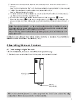
4. Installing Wireless Receiver .................4

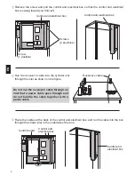
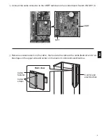
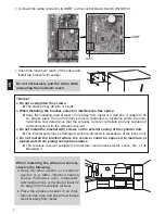
4.1 Connecting to Cylinder unit ..............4
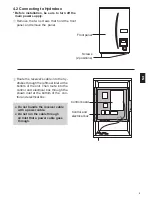
4.2 Connecting to Hydrobox ...................8

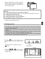
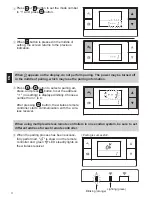
5. Pairing process ...................................10
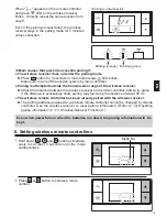
6. Setting wireless remote controllers.....12

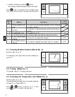
6.1. Viewing Address Number ..............13
6.2. Pairing  ..........................................13
6.3. Selecting the Temperature Unit  ...13

Contents

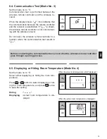
6.4.Communication Test ......................14
6.5. Displaying or Hiding Room Temperature ...14
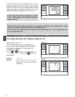
6.6 Automatic Zone No. Display .............15

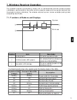
7. Wireless Receiver Operation ..............16

7.1.Functions of Buttons and Displays ..16
7.2.Turning on Power ...........................17
7.3.Wireless Receiver Functions ..........17

8. FAQ ....................................................18
9. 

Specifications

 .....................................19

10. Supplementary information...............19

1

 Warning

►Installation

Do not use the device in particular en-

vironments.

Do not use the device in particular environments 

where the following substances are present in 

large amounts: oil, vapour, organic solvent, corro-

sive gas (such as ammonia, sulphuric compounds, 

and acid or the like), or where acid or alkali solu-

tion, or particular sprays are used frequently. This 

could affect operating performance, or cause 

corrosion, which could result in electrical shock, 

breakdown, smoke generation, or fire.

Do not place the devices in an environ-

ment where flammable gas may occur, 

stay, flow in, or leak.

Build-up of flammable gas could result in fire or 

explosion.

1. Safety Precautions

● The precautions mentioned below are important to use the device safely. Be sure to under

-

stand and follow them. 

● 

The following hazardous classification shows the likelihood and severity of hazards if a per-

son does not follow the instructions contained on the following signs.

 Warning

Indicates a hazardous situation which, if a person does not follow the instruc-

tions, could result in death or serious injury.

 Caution

Indicates a potentially hazardous situation that, if a person does not follow the 

instructions, may result in bodily injury or property damage.

This manual explains installation of the PAR-WR51R-E wireless receiver and the 

PAR-WT50R-E wireless remote controller, and settings of these devices. Before in-

stalling the devices, read this manual thoroughly. After reading, be sure to hand this 

manual to the user.

Summary of Contents for PAR-WR51R-E

Page 1: ...lvorens de PAR WT50R E en PAR WR51R E apparaten te installeren VOOR DE INSTALLATEUR Manual de Instalação e Definição Para uma utilização segura e correcta é favor ler cuidadosamente este manual antes de instalar os dispositi vos PAR WT50R E e PAR WR51R E PARA O INSTALADOR Manual de instalación y configuración Para un uso correcto y seguro de los dispositivos PAR WT50R E y PAR WR51R E lea este manu...

Page 2: ... or particular sprays are used frequently This could affect operating performance or cause corrosion which could result in electrical shock breakdown smoke generation or fire Do not place the devices in an environ ment where flammable gas may occur stay flow in or leak Build up of flammable gas could result in fire or explosion 1 Safety Precautions The precautions mentioned below are important to ...

Page 3: ...tors Please dispose of this equipment batteries and accumulators correctly at your local community waste col lection recycling centre Please help us to conserve the environment we live in Warning The device must be installed by a dealer or an authorised technician ac cording to the appropriate installation manual If the device is installed improperly electric shock or fire could result Do not plac...

Page 4: ... hereinafter abbreviated as OM Ecodan system installation manual hereinafter abbreviated as IM 2 Installing and setting procedure Power off the ecodan system Install the wireless receiver on the ecodan system See 4 Installing the Wireless Receiver in this manual When installing the wireless receiver be sure to set the SW1 8 on the control board to ON See 5 1 DIP Switch Functions in IM Power on the...

Page 5: ...e 4 Before Operation in OM To set the wireless remote controller as a room sensor that monitors room temperature see Main remote controller Options in IM Use the main controller to set the ecodan system to the room temp mode When the flow temp mode or the compensation curve mode is selected the wireless remote controller will operate as a thermostat See Main remote controller in IM When the remote...

Page 6: ...ical box Control and electrical box Screws 2 positions Do not run the receiver s cable through an inlet that a power cable goes through and do not bundle the cable together with a power cable Route the cable out the back of the control and electrical box and run the cable into the box through the shown inlet in the underside of the box Control and electrical box Control and electrical box Control ...

Page 7: ...l board Switch ON SW1 8 Remove excessive slack on the cable then secure the cable with a cable fastener and 2 ca ble straps on the upper side and center on the back of control and electrical box CNRF SW1 Control and electrical box Back view Cable straps Cable fastener ...

Page 8: ...ould cause electric shock fire or its breakdown 7 Check the maximum reach of the cable and install the bracket on the wall with screws Place the control and electrical box back in the original position and reinstall the 3 screws Place the wireless receiver on the fixed bracket Hook the holes on the back of the wireless re ceiver onto the projections on the bracket and fix the wireless receiver in ...

Page 9: ...remove the panel Screws 2 positions Front panel Route the receiver s cable into the hy drobox through the leftmost inlet at the bottom of the unit Then route into the control and electrical box through the shown inlet at the bottom of the con trol and electrical box Do not bundle the receiver cable with a power cable Do not run the cable through an inlet that a power cable goes through ...

Page 10: ...ten the screws The bracket may deform or break When installing the bracket select an interference free space Keep the installing area at least 10 cm away from metal or a wall box If unable to do so always place the room wireless remote controllers in locations where the com munication test determines that the wireless remote controllers are fully capable of communication with the wireless receiver...

Page 11: ...ote controller is not paired the indoor unit cannot be operated using the remote controller Before using the wireless remote controllers always ensure to go through a pairing process Pairing is NOT possible unless the ecodan system is off When the ecodan system is ON be sure to turn it off before starting the pairing process The wireless receiver is also needed for pairing so please make sure to o...

Page 12: ... shown on the remote controller and green LED steadily lights on the wireless receiver Pairing is successful Lighting green Blinking orange Press or button to set the mode number to 1 and press button When button is pressed in the middle of setting the screen returns to the previous indication Press or button to select a pairing ad dress and press button to set the address no setting is displayed ...

Page 13: ...n already paired with the wireless receiver The pairing address assigned to a wireless remote controller cannot be changed by remote controller Use the wireless receiver to reset pairing information Refer to 3 Resetting pairing information in 7 3 Wireless Receiver Functions Even when power fails or when the batteries run down the pairing information will be kept When appears on the remote controll...

Page 14: ... re ceiver 2 Temperature unit To select C or F C 3 Communication test Communication test with the wireless receiver 4 Room temperature display Actual room temperature display OFF 5 Automatic zone no display To enable or disable automatic zone no display OFF 6 1 Viewing Address Number Mode No 0 Set the mode no to 0 The display to the right shows that the address is set to 2 Confirm setting by press...

Page 15: ...tablished If is shown the wireless remote controller is not communicat ing with the wireless receiver Do not leave the wireless remote controller in a location where the communication test results in When the actual room temperature is NOT displayed When the actual room temperature is displayed 6 5 Displaying or Hiding Room Temperature Mode No 4 Set the mode no to 4 Select either displaying or hid...

Page 16: ...stalled on a bracket room temperature might not be accurate being affected by the wall temperature Perform a test run and place the remote controller where the room temperature can be correctly detected 15 Inactive Active 6 6 Automatic Zone No Display Mode No 5 Set the mode no to 5 When the automatic zone no display is ac tive a zone number assigned to the remote controller is displayed for 3 seco...

Page 17: ...switch operating mode Communication LED green To indicate that the wireless re ceiver is communicating Operation LED orange To show operating status of the wireless receiver The following table shows the operating and illuminating status of the LEDs Operation LED orange Communication LED green Description Blinking Blinking Power is ON for 3 seconds Off Off Normal mode Not paired Off On Normal mode...

Page 18: ...ess remote controller green LED comes on When the wireless receiver is com municating with a wireless remote controller green LED blinks 2 Pairing mode For details refer to 5 Pairing process in this manual 3 Resetting pairing information Once pairing information has been cleared ALL the wireless remote controllers need go through a pairing process again Hold down button for 5 seconds or more until...

Page 19: ...res should be taken when the room temp display indicates 2 with The thermistor inside the wireless remote controller has a fail ure Check the resistance of the thermistor When the room temperature is between 0 and 40 C the resistance must be between 5 and 28 kΩ What measures should be taken when the room temp display indicates 3 with A communication error occurs between the wireless remote control...

Page 20: ...ely The room sensor is used for monitoring room temperature The selection of room sensor can be fixed or changed according to time using a schedule timer Note Room sensor can be selected by main controller only 9 Specifications Item Description Power source 12V DC powered by indoor unit Operating temperature and humidity re quirements Temperature 0 to 40 C Humidity 30 to 90 RH No condensation Weig...

Page 21: ...ded for use in the residential commercial and light industrial environment The product at hand is based on the following EU regulations R TTE Directive 1999 5 EC HEAD OFFICE TOKYO BLDG 2 7 3 MARUNOUCHI CHIYODA KU TOKYO 100 8310 JAPAN Authorized representative in EU MITSUBISHI ELECTRIC EUROPE B V HARMAN HOUSE 1 GEORGE STREET UXBRIDGE MIDDLESEX UB8 1QQ U K ...

Reviews: