


SERVICE MANUAL
CONTENTS
1. REFERENCE MANUAL ·······································2
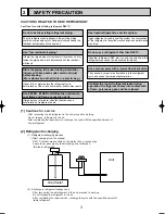
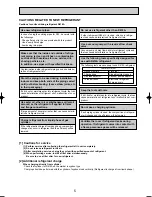
2. SAFETY PRECAUTION ·······································3
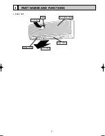
3. PART NAMES AND FUNCTIONS ·······················7
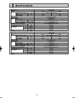
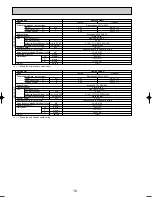
4. SPECIFICATIONS ················································9
5. NOISE CRITERION CURVES ····························11
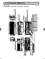
6. OUTLINES AND DIMENSIONS ·························12
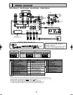
7. WIRING DIAGRAM ············································13
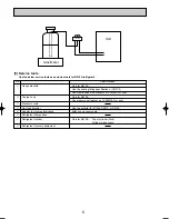
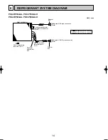
8. REFRIGERANT SYSTEM DIAGRAM······················14
9. TROUBLE SHOOTING ······································15
10. DISASSEMBLY PROCEDURE ··························30
11. PARTS LIST ·······················································34
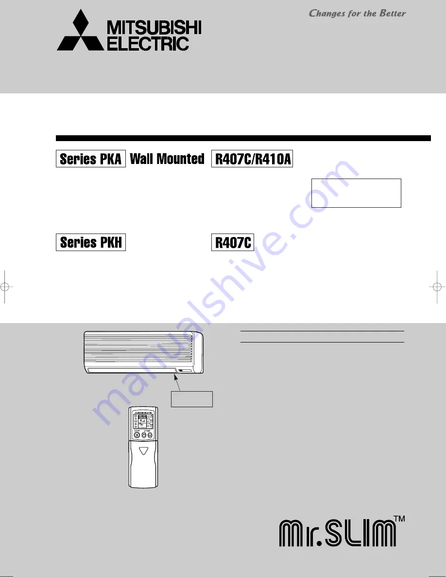
Indoor unit
[Model names]
PKA-RP35GAL
PKA-RP50GAL
[Service Ref.]
PKA-RP35GAL
PKA-RP50GAL
Indoor unit
No.OC330
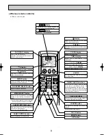
Remote controller
•
This manual describes only
service data of the indoor
units.
SPLIT-TYPE, HEAT PUMP AIR CONDITIONERS
SPLIT-TYPE, AIR CONDITIONERS
Model name
indication
PKH-P35GALH
PKH-P50GALH
PKH-P35GALH
PKH-P50GALH
April 2005
OC330--1.qxp 05.5.9 1:30 PM Page 1


