background image

From the library of: Superior Sewing Machine & Supply LLC

Summary of Contents for PLK-A2016F

Page 1: ...ANCINGI NinSUBiSHl ELECTRIC MITSUBISHI Industrial Sewing Machine INSTRUCTION MANUAL Sewing Machine Electronic Pattern Sewing Machine PLK A2016F PLK A2016FL A180E257P01 From the library of Superior Sewing Machine Supply LLC ...

Page 2: ...nd how to prepare the sewing patterns reference should be made to the Instruction Manual below Mitsubishi Industrial Sewing Machine Instruction Manual Control Unit A180E243P01 No part of this manual may be copied or transcribed without written permission from Mitsubishi Electric Corporation The contents of this manual are subject to change without notice Every effort was made to ensure that the co...

Page 3: ...ol box 15 4 6 Power cord for work lamp 16 4 7 Connecting the power cable 17 4 8 Changing the direction of the motor rotation 17 5 PREPARING TO OPERATE AND PRECAUTIONS 19 6 CHECKPOINTS FOR OPERATION 20 7 HANDLING THE SEWING MACHINE HEAD 23 7 1 Lubrication 24 7 2 Installing the needle 25 7 3 Threading the needle thread 26 7 4 Winding the bobbin thread 26 7 5 Installing the bobbin 27 7 6 Installing t...

Page 4: ...er and hook 35 9 4 Adjusting the thread guide above hook 37 9 5 Adjusting the presser foot 39 9 6 Adjusting the wiper drive mechanism 41 9 7 Adjusting the home position 43 9 8 Maintaining and inspecting the X Y table 47 9 9 Adjusting the X Y table belt tension 49 9 10 Adjusting the synchronizer 51 9 11 Adjusting the thread trimmer 53 9 12 Adjusting the trimmer thread tail length 55 9 13 Adjusting ...

Page 5: ...6F and PLK A2016AF are configured with the parts shown below PHOTO PLK A2016F Head rest Table LIMl STOP Z motor Foot switch Machine head Cotton stand Control box Fig 1 1 From the library of Superior Sewing Machine Supply LLC ...

Page 6: ...g large numbers of stitches Easy adaptability to automatic machine External interface functions for use as an application machine or special purpose machine are optionally provided 2 Less dependency on skills or training required Simple input and operation thanks to interactive system The liquid crystal display LCD vastly simplifies the preparation of the sewing patterns and the preparations made ...

Page 7: ...well defined seams and stitches Resolution in 0 1 mm units By bringing the resolution of the fabric feed mechanism accurately down to a 0 1 mm pitch it is now possible to sew both smoothly and precisely Maximum stitch length of 12 7 mm The variable stitch length accommodates everything from stitches where a delicate touch is required such as in embroidery to large pitch sewing of such articles as ...

Page 8: ...r large sized hook Thread trimmer Combination of fixed knife and movable knife plane scissoring Lubrication system Manual oiling and replenishment with oil braid Tank type Oil used White spindle oil No 2 Sewing area PLK A2016F 200mm in X cross wise direction 160mm in Y lateral direction PLK A2016FL 250mm in X cross wise direction 190mm in Y lateral direction Max sewing speed 2 000 spm for feed len...

Page 9: ...cal home position Set by optical sensor and insulator Mechanical home position correction 0 1 to 12 7 mm 0 1 mm unit adjustable Second home position Set by input program Halt Set by input program Reverse rotation shaft output Set by input program Baste stitching Set by input program Test function Jog switch Format function Format can be made using 3 5 floppy disk 2HD type Error display Various err...

Page 10: ...peed MD2 low speed L Correction Stitch number reduction Stitch number addition 1 stitch correction Speed change Function change 1 or N stitches reduced from last stitch 1 or N stitches reduced from middle stitch deletion of data from assigned position to the last stitch 1 stitch added at assigned position 1 stitch corrected at assigned posi tion Speed change of N stitches from assigned position sp...

Page 11: ... large hook For standard hook For light fabric 1 6 mm dia MS03A0101 Outer dia 3 5 mm ID 2 0 MV30A1256 7 For medium heavy fabric standard For DB standard MF10E0210 2 2 mm dia MS03A1101 Outer dia 4 5 mm ID 3 0 MV30A0256 Standard MS01A0616 MS17A0120 MS01A0120 MS17A0125 MS09E0125 MS17A0123 MS09A1123 For heavy fabric For DB heavy fabric MF82E0210 2 6 mm dia MS03A2101 For heavy fabric MS01A1616 MS17A112...

Page 12: ...hine in a standing position I Loosen the bolts 5 units at the left and 5 units at the right used to secure the stand d Lift the table to the desired height and then secure it properly using the bolts for securing the stand Notes The table height should be changed before the machine head is installed D If the table height must be changed after the machine head has been installed detach the head fro...

Page 13: ... Fig 4 2 Hinge A 4 2 Assembling the machine head see Figs 4 4 4 5 1 Insert the accessory head rest into the corresponding holes provided on the table 2 Insert the two hinges B into the machine head which has been removed from its packing box 3 Place the head on the table so that it rests on the six rubber pads and two hinges 9 From the library of Superior Sewing Machine Supply LLC ...

Page 14: ...pecial bolt for the belt cover large at the rear of the machine 9 Secure the accessory belt cover large to the machine using the screws provided 10 Secure the accessory belt cover small to the table using the wood screws 3 units Notes Checkpoints for carrying sewing machine D Front of sewing machine Be sure to use the two handles left and right to hold the machine Under no circumstances should the...

Page 15: ...t cover large Belt cover small Hinge B Hinge A Cords and air tubes pi Oil pan Fig 4 4 Rubber pad Handle Wood screw Table Oil pan Oil bottle Fig 4 5 11 From the library of Superior Sewing Machine Supply LLC ...

Page 16: ...ntrol knob and turn After setting press down the knob 4 Disconnecting the air tubes To disconnect air tube push the end of tube forward and while holding down the fitting sleeve pull the tube 5 The air tubes for the work holder and presser foot are as shown in Fig 4 7 Control knob Air pressure gauge Fig 4 6 Pressure foot Clamp frame Fig 4 7 12 T T Joint Solenoid valve Filter regulator Drain knob I...

Page 17: ...s no mate connector Insert it into the solenoid valve installation plate and fix 4 Connectors X and Y are for the stepping motor Remove the motor cover on the left of the sewing machine and connect to the stepping motor 5 Connector F is for the wiper solenoid 6 Connector M is for the tension release solenoid 7 Connector G is for the X Y sensor and the halt switch 2 Neatly bundle the connected lead...

Page 18: ...on socket head bolts 4 Mount the control box on the stand rest and use the screws 4 units to secure it from behind the rest 5 Pass the control box cord along the stand support and secure it in two places with the nylon clip 6 At the rear of the stand a cable through hole in the table 7 Fit and lock the connector of the control box cord into the connector marked control panel at the rear of the con...

Page 19: ...lamp will not be used its two leads must be insulated to prevent shortcircuiting As in the figure on the right proceed as for 1 or 2 and be sure to insulate the leads Shortcircuiting may result in a burn out of the motor winding Insulating tape Phase re versing plug LIMI STOP Z motor stripped wire Insulating tape 2 or 3 turns Insulating tape 2 or turns cut stripped lead Min 10 mm Lamp leads Lamp l...

Page 20: ...e phase power supply and the accessory conversion plug for conversion from 3 pins with ground to 2 pins are used 3 When a single phase motor is used do not plug the power cord into a branch socket but to a wall outlet Notes All leads should be bundled together and secured so that they will not come into contact with the V belts 2 The plugs and connectors must be securely connected 3 The power plug...

Page 21: ... phase motor to stop completely after the power has been turned off remember to switch on the power after it has stopped The direction of the motor rotation will remain unchanged if the power is turned on while the motor is running Phase reversing plug Fig 4 10 Note Be sure to set the power switch to the OFF position when disconnecting the power plug 17 Direction of rotation From the library of Su...

Page 22: ...needle is always located within the frame of the work holder Make sure that the needle is set at the center of the presser foot 5 Position of work holder The relationship between the work holder and home position is such that the home position is not at the center of the work holder but deviates to the right of center by a dimension equivalent to the allowance for the presser foot as shown in Fig ...

Page 23: ...ake care not to allow water or any other liquid substance from entering the machine head and control unit and to keep metal waste and other conductive materials away from the sewing machine The sewing machine cannot be used in an atmosphere where it will be exposed explosive gases dust or oily vapors D Avoid using the sewing machine in a location where it will be exposed to excessive shock or vibr...

Page 24: ...limit Stitch length mm Maximum speed limit spm 0 1 to 3 0 2 000 3 1 to 3 5 1 820 3 6 to 4 0 1 670 4 1 to 4 5 1 430 4 6 to 5 0 1 250 5 1 to 6 5 1 000 6 6 to 9 0 800 9 1 to 12 7 600 400 200 2 When a single phase motor is being used do not perform the start operation immediately but wait about 10 seconds after the power has been switched on until the motor operation stabilizes Burnouts may be caused ...

Page 25: ...r TV set near the sewing machine may cause noise interference in the reception of the radio or TV broadcast In cases like this use a different power supply or place the radio or TV set at a distance from the sewing machine 6 Inspection of control circuitry D Avoid using a multimeter to inspect the internal control circuitry since the voltage from such may damage the semiconductor parts 7 Up turn o...

Page 26: ...Up turn of head V belt 7 HANDLING THE SEWING MACHINE HEAD Names of major parts of machine head Presser foot Thread tension adjusting screw regulator Halt switch Eye guard Slide plate Needle plate viium Bobbin winder Belt cover small Fig 6 2 Synchronizer Y synchronizer cover Oil gauge Work Clamp holder unit Feed plate X Y cover X Y cover bottom top Fig 7 1 22 From the library of Superior Sewing Mac...

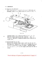
Page 27: ...wing machine has been installed Fig 7 2 Normally lubricant is supplied automatically from the oil supply tank 2 Replenishing the oil tank Replenish oil through supply ports K and L on the arm side and head side respectively until the oil reaches the round red mark in the center of the oil gauge Excessive supply may cause oil to spill from the supply ports when the head is tilted 23 From the librar...

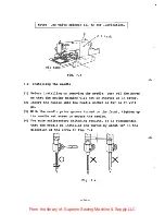
Page 28: ... 2 Insert the needle into the needle socket as far as it will go 3 With the needle prime groove turned to the front tighten up the needle set screw to secure the needle 4 For more satisfactory stitching results it is recommended that the needle be installed and turned by about 10 in the direction of the arrow in Fig 7 4 M r Clearance DS 2 3 o V X X I Fig 7 4 24 From the library of Superior Sewing ...

Page 29: ... needle Arm thread guide Thread Take up spring Tension discs Top thread guide Fig 7 6 7 4 Winding the bobbin thread 1 Pass the thread coming from the spool holder base as shown in Fig 7 7 and wind the end of the thread around the bobbin by several turns in the direction of arrow a Fig 7 7 25 From the library of Superior Sewing Machine Supply LLC ...

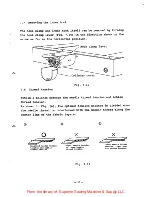
Page 30: ...nt to approximately 600 spm 6 Upon completion of the thread winding press the bobbin winder key again This turns the LED off 7 5 Installing the bobbin 1 Place the bobbin B inside the bobbin case A 2 Put the thread E into the slit C and pass it through the eyelet D See Fig 7 8 7 6 Installing the bobbin case 1 Set the needle bar to its highest position and open the bottom cover See Fig 7 9 2 Open th...

Page 31: ...etween the needle thread tension and bobbin thread tension As shown in Fig A the optimum tension balance is yielded when the needle thread is interlocked with the bobbin thread along the center line of the fabric layers O Balanced needle thread tension and bobbin thread tension X Tight needle tension or loose bobbin thread tension Fig 7 11 27 Loose needle thread tension tight bob bin thread tensio...

Page 32: ...on adjusting screw To increase To reduce Bobbin case Fig 7 12 Fig 7 13 Tension regula ting thumb nut To increase To reduce Note Excessive tension may result in puckering or a broken thread 7 9 Adjusting the work holder 7 9 1 Adjusting the work holder pressure The work holder pressure is generated by a pneumatic air system and it can be adjusted by turning the air pressure regulator knob See Fig 4 ...

Page 33: ...ork holder arm pin 2 To install the replacement work holder engage its U groove with the work holder arm pin Then check that there is no play in the direction indicated by the arrow The existence of play may cause a shift in the stitches Work holder arm U groove Pin Work holder Fig 7 14 29 From the library of Superior Sewing Machine Supply LLC ...

Page 34: ... move it up The vertical stroke can be increased up to 10 mm 4 To adjust the pressure of the presser foot loosen the thumb nut in Fig 7 16 and turn the presser foot adjusting screw The pressure increases when the screw is turned clockwise and reduced when it is turned counterclockwise The figure shows the standard adjustment Normally there is no need for the auxiliary adjusting screw to be touched...

Page 35: ...older loosen screws A and B and adjust Lower clamp plate Screw B Work holder arm Guide plate Screw A Fig 7 17 7 12 Lubrication with silicone oil When applying silicone oil to the needle thread mount the thread guide with the felt area onto the bottom part of the face plate as shown in Fig 7 18 and supply the oil to the felt area Face plate Needle thread Thread guide with felt area Fig 7 18 31 From...

Page 36: ...ion of arrow a with the thread wound up to 80 of its full volume on the bobbin Shaft Bobbin Adjust lever Fig 9 1 2 Adjusting the turning of the bobbin Loosen screws C and D of the winder bobbin complete mount onto the shaft a bobbin on which thread has been appropriately wound and push the adjust lever in the direction of arrow b Next move the bobbin winder complete in the direction of arrow c in ...

Page 37: ...sition using the needle bar connecting stud set screw Set mark B against the bottom of the metal when the DPx5 type of needle is used There are 4 timing marks one of which is selected to correspond with the type of needle used Needle bar connecting stud set screw Face plate Needle bar metal Timing mark on needle bar For DPx5 For DPX17 Fig 9 3 Fig 9 2 9 3 Adjusting the driver and hook 1 Use an Alle...

Page 38: ...to 0 05 mm is created between the head of the inner hook and needle See Fig 9 6 The rotating hook can be moved by first loosening its set screw and then turning the eccentric pin using a slot head screwdriver i Rotating hook set screw Eccentric pin Fig 9 5 0 05 O lmm 5 Fig 9 6 4 In this condition adjust the longitudinal position of the driver so that the clearance between the driver and and needle...

Page 39: ...e hook so that its left and right shoulders are aligned with the side surface of the needle A failure in thread trimming may result if this position should shift out of alignment 2 Adjust the thread guide so that a clearance standard 0 8 mm between the hook retainer and thread guide is created which will permit the needle thread to pass through easily A failure in thread trimming may result if thi...

Page 40: ...ad guide surfaces with which the thread comes into contact greatly affects the thread tension and thread trimming performance Thread guide set screw 0 8mm Needle Thread guide Shoulders Thread guide set screw 0 Hook retainer Fig 9 9 36 From the library of Superior Sewing Machine Supply LLC ...

Page 41: ...ric ring B and turn the pulley slowly to position ring B 5 The timing is increased when the pulley is turned in the forward direction of arrow D conversely it is reduced when it is turned in the other direction 6 After the adjustment press down on the eccentric ring B in the direction of the arrow while tightening up set screws A and C in that order 7 Position and secure the upper vertical feed cr...

Page 42: ... of the inside presser foot in the halt status will increase by between 1 and 2 mm Since the height of the inside presser foot also changes loosen the presser bar set screw to readjust the height of the presser bar 2 Since the amount of noise and vibration increase in direct proportion to the extent of the vertical stroke it is recommended that the stroke be adjusted to as low as possible Bell cra...

Page 43: ... and 0 5 mm to prevent stitch skipping this clearance can be reduced by lowering the presser foot However noise will increase somewhat when the fabric is pushed down by the presser foot Moreover since an increase in the fabric holding time adversely affects the needle thread tension and seam tightness and since the fabric may be caught by the presser foot to throw the pattern into disarray the low...

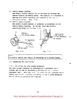
Page 44: ... the thread wiping position of the wiper to the dimension shown in Fig 9 13 when drive crank has been stopped at the above position Screw Stopper Washer Fig 9 12 Stopper Driven Rotary crank solenoid V Drive crank Driven crank pin Slotted hole Driven crank otary solenoid Drive crank Fig 9 13 Driven crank Wiper Fig 9 14 40 Mm 5 mm Presser foot From the library of Superior Sewing Machine Supply LLC ...

Page 45: ...ustment 1 Set SW3 switch 2 in the control panel to the ON position If this switch is OFF the effective sewing area will be reduced by an amount equivalent to the movement of the home position Example Stitching will not be possible in the shaded area shown below if the home position is moved 60 mm in the X direction and 40 mm in the y direction Initial home position Effective sewing area X directio...

Page 46: ... to the right by moving the X axis synchronizer in the direction of arrow C and the detector plate in the direction of the arrow The detector plate can be moved only by a distance equivalent to the length of its slotted hole Additional movement of the X axis synchronizer beyond the dimension of the slotted hole is possible by removing screws A and changing the position of the holder base screw 3 F...

Page 47: ...Detector plate Detector plate set screw Screw A Screw B Fig 9 17 43 X axis synchronizer Holder base Home position fine adjusting screw From the library of Superior Sewing Machine Supply LLC ...

Page 48: ...by turning the home position fine adjusting screw after set screw A has been loosened Adjustable distance 3 mm 5 After the adjustment check that the synchronizer plate passes through the center of the synchronizer without making contact and that it passes through the synchronizer in the perpendicular direction as well 6 Set the HOME key to ON perform home position return and check that the home po...

Page 49: ... oil runs out or if the grease dries out this will results in increased sliding resistance which in turn results in a deterioration of the smoothness of operation and accuracy of the response When the sewing machine has not been used for a prolonged period of time inspect the raceway surfaces 3 Since the X Y table vibrates strongly during sewing operations and this may loosen the screws it is reco...

Page 50: ...rfaces and tighten each of the screws successively in turn and repeat this procedure until they are all tightened up evenly together Securing the slide units Press all the slide units firmly against the mounting surfaces and secure them D Securing the track rails at the driven side Move the X Y table and while checking that it moves smoothly secure the track rails at the driven side Proceed to tig...

Page 51: ...ill be maintained 9 9 Adjusting the X Y table belt tension 9 9 1 Adjusting the X axis belt tension 1 Loosen the four bracket clamping screws and turn the belt tension adjusting screw to adjust the belt tension 2 To increase the X axis belt tension tighten up the X axis belt tension adjusting screw located at the side of the bed The recommended belt tension is such that no slack is detected when th...

Page 52: ...s belt tension adjusting screw The recommended belt tension is such that no slack is detected when the belt is pushed down lightly This tension is attained by turning the adjusting screw by about 90 from a position where it is stiff to the touch Bracket clamping bolt Cover plate Y axis belt tension adjusting screw Fig 9 21 48 From the library of Superior Sewing Machine Supply LLC ...

Page 53: ...g clockwise delays the stop position conversely turning it counterclockwise advances the stop position 3 If the needle bar stop comes too early the needle thread may disengage from the needle eye when stitching is commenced Conversely if it is delayed the needle will stop at a lower position which may mean that the wiper will be caught by the needle or that the movable knife will not move since th...

Page 54: ...etecting discs The front disc red is used to detect the DOWN position the middle disc black to detect the UP position and the rear disc blue to time the thread release 3 The middle disc black has a scale Align the triangular mark of the front disc red at the 115 position on this scale and the triangular mark of the rear disk blue at the 340 position Red disc DOWN Black disc UP Blue disc thread pos...

Page 55: ...until it makes contact with the cam follower frank stop per loosen the stopper screw by about one third of a complete turn and then tighten up the nut Stopper screw Stopper Cam groove Approx 1 mm Cam groove Thread trimmer cam l Nut Cam follower crank Roller Arm shaft Shoulder Fig 9 25 4 To remove the knife assembly remove the E type stop ring in Fig 9 26 the feed plate shown in Fig 7 1 and the fou...

Page 56: ...screw shown in Fig 9 9 Moreover if it is located too close to the hole the trimmed needle thread tail may be sandwiched between the fixed knife and movable loiife E type stop ring Movable cnife D O bmm Fig 9 26 Hook retainer Fixed knife Knife drive crank 52 J p Movable knife posi tion adjusting screw Fig 9 27 From the library of Superior Sewing Machine Supply LLC ...

Page 57: ...icularly true with thin thread will rub against the fixed knife blade and that it may break or that the bobbin and needle threads will be shortened before the knife blade engages To prevent this install the fixed knife at a distance from the needle plate hole or remove the spacer below the needle plate to create a clearance of 0 2 mm or less between the fixed knife and needle plate Care should be ...

Page 58: ...nm Fig 9 30 4 Thread release occurs when the presser foot rises the work holder is at the home position when the power is switched ON or the fabric is fed without stitching and when threads are trimmed 5 Adjusting the amount of thread release during thread trimming To adjust remove the top cover loosen nut C shown is Fig 9 31and move the wire tube The opening of the discs will increase when Turned...

Page 59: ... screw B 2 Turn the tension regulating thumb nut C clockwise or counterclockwise to adjust the stroke of the take up spring and then tighten up screw B after the adjustment Turn to the right to increase the stroke Turn to the left to reduce the stroke 10mm D 9 32 55 From the library of Superior Sewing Machine Supply LLC ...

Page 60: ...lt tension 1 Remove the belt cover 2 Loosen the two nuts shown below 3 Adjust the motor position using the upper nut so that the appropriate tension is yielded in the belt by the gravity of the motor After the adjustment tighten up the lower nut V belt Nuts Belt cover LIMI STOP Z motor Fig 9 33 56 From the library of Superior Sewing Machine Supply LLC ...

Page 61: ...ectric corporation HEAD OFFICE MITSUBISHI OENKI BLOG MARUNOUCHI TOKYO 100 TELEX J24S32 CABLE MELCO TOKYO 9210 MEE Specifications subiject tochange without notice From the library of Superior Sewing Machine Supply LLC ...

Reviews: