background image

User's Manual

Q6TA32

Thank you for purchasing the Mitsubishi programmable controller 
MELSEC-Q series.

  © 2002 MITSUBISHI ELECTRIC CORPORATION

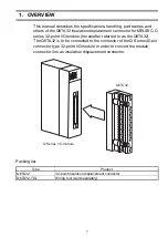
Insulation Displacement Connector for

MELSEC-Q Series 32-Point I/O Module

Prior to use, please read this and relevant manuals thorougly to fully 
understand the product.

MODEL

Q6TA32-U-JE

MODEL

CODE

13JT92

IB(NA)-0800228-F(1806)MEE

Summary of Contents for Q6TA32

Page 1: ...oller MELSEC Q series 2002 MITSUBISHI ELECTRIC CORPORATION InsulationDisplacementConnectorfor MELSEC QSeries32 PointI OModule Prior to use please read this and relevant manuals thorougly to fully unde...

Page 2: ...they are important for personal and system safety Make sure that the end users read this manual and then keep the manual in a safe place for future reference DESIGN PRECAUTIONS CAUTION Do not bunch t...

Page 3: ...ply for the system in all phases before mounting or removing this product Otherwise the I O module may go down or malfunction WARNING Shut off the external power supply for the system in all phases be...

Page 4: ...CAUTION Do not disassemble or rebuild this product It may cause accidents malfunction injury or fire Shut off the external power supply for the system in all phases before mounting or removing this pr...

Page 5: ...NDED OR EXCLUDED BY INSTRUCTIONS PRECAUTIONS OR WARNING CONTAINED IN MITSUBISHI S USER INSTRUCTION AND OR SAFETY MANUALS TECHNICAL BULLETINS AND GUIDELINES FOR the PRODUCT Prohibited Application Prohi...

Page 6: ...s provided that the usage of the PRODUCT is limited only for the specific applications agreed to by Mitsubishi and provided further that no special quality assurance or fail safe redundant or other sa...

Page 7: ...hapter 1 2 3 4 Section 5 2 Oct 2011 IB NA 0800228 D SAFETY PRECAUTIONS Chinese May 2015 IB NA 0800228 E Model addition Jun 2018 IB NA 0800228 F Descriptions are revised due to compliance with the Chin...

Page 8: ...CONTENTS 1 OVERVIEW 1 2 PERFORMANCE SPECIFICATIONS 2 3 NAMES OF PARTS 3 4 HANDLING INSTRUCTIONS 5 5 WIRING 6 5 1 Wiring Instructions 6 5 2 External Wiring 7 5 3 Wiring Procedure 8 6 EXTERNAL DIMENSION...

Page 9: ...8 MANUALS The following manual is related to this product Please order it if necessary Related manual Manual Name Manual Number Model Code I O Module Type Building Block User s Manual SH 080042 13JL9...

Page 10: ...A 9 Memo...

Page 11: ...le hereinafter referred to as the Q6TA32 The Q6TA32 is to be connected to the connector of the Q Series 40 pin connector type 32 point I O module in order to convert the module connector into an insul...

Page 12: ...S2 QX71 QY41P QY41H QY71 Applicable wire 2 Polyvinyl chloride wire twisted wire Nominal 0 5 mm2 20AWG max insulation diameter 1 9 mm 0 07 inch Number of connectable wire 1 Tensile strength 1 of wire...

Page 13: ...displacement terminals 4 Terminal number Line B Indicate the I O module pin number B1 to B20 corresponding to the insulation displacement terminals 5 Cover fixing screw Screw for fixing the cover M2...

Page 14: ...4 Memo...

Page 15: ...g screws within the following ranges 5 When the Q6TA32 is installed to the I O module it is 9 mm 0 35 inch out of the I O module bottom Refer to 6 OUTLINE DRAWING Pay attention to the installation pos...

Page 16: ...g the adjacent modules connect them after pulling them toward you within the wire s tensile strength range given in the performance specifications 5 During and after wiring do not apply loads larger t...

Page 17: ...ignal name Terminal number Signal name B20 X00 A20 X10 B20 Y00 A20 Y10 B19 X01 A19 X11 B19 Y01 A19 Y11 B18 X02 A18 X12 B18 Y02 A18 Y12 B17 X03 A17 X13 B17 Y03 A17 Y13 B16 X04 A16 X14 B16 Y04 A16 Y14 B...

Page 18: ...de inside the Q6TA32 without a gap push it in gently with your finger to temporarily hold it and push it far enough with the wiring tool When wiring Line A right side check the numeral of Line B left...

Page 19: ...heck 2 Disconnecting the wire Loosen the cover fixing screws remove the covers and pull the wire toward you Cover fixing screw I O module I O module Wire Wire Covers Q6TA32 Wire Q6TA32 Wire Tester lea...

Page 20: ...10 6 EXTERNAL DIMENSIONS 1 Q6TA32 When mounted on an I O module 2 Q6TA32 TOL 98 3 86 93 5 3 68 27 4 1 08 25 0 99 37 1 46 90 3 55 9 0 35 Unit mm inch 93 3 66 50 1 97 9 5 0 37...

Page 21: ...11 Memo...

Page 22: ...12 Jakarta Pusat 10340 Indonesia Tel 62 21 3192 6461 MITSUBISHI ELECTRIC INDIA PVT LTD Pune Branch Emerald House EL 3 J Block M I D C Bhosari Pune 411026 Maharashtra India Tel 91 20 2710 2000 USA MIT...

Reviews: