background image


2

22

2Unpacking to Installation

Unpacking to Installation

Unpacking to Installation

Unpacking to Installation


Confirming the operation

Confirming the operation

Confirming the operation

Confirming the operation

   2-

   2-

   2-

   2-29

29

29

29

(5) 

(5) 

(5) 

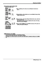
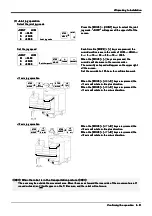
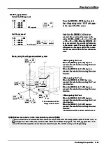
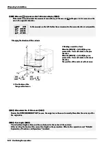
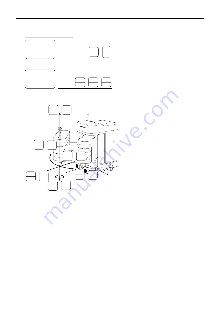
(5) Cylindrical jog operation

Cylindrical jog operation

Cylindrical jog operation

Cylindrical jog operation

Press the [MOVE] + [XYZ] keys, and then press 

Press the [MOVE] + [XYZ] keys, and then press 

Press the [MOVE] + [XYZ] keys, and then press 

Press the [MOVE] + [XYZ] keys, and then press 
only the [XYZ] key. "CYLNDER" will appear at the 

only the [XYZ] key. "CYLNDER" will appear at the 

only the [XYZ] key. "CYLNDER" will appear at the 

only the [XYZ] key. "CYLNDER" will appear at the 
upper left of the screen.

upper left of the screen.

upper left of the screen.

upper left of the screen.

Each time the [MOVE] + [+] keys are pressed, the 

Each time the [MOVE] + [+] keys are pressed, the 

Each time the [MOVE] + [+] keys are pressed, the 

Each time the [MOVE] + [+] keys are pressed, the 
override will increase in the order of LOW 

 HIGH 

override will increase in the order of LOW 

 HIGH 

override will increase in the order of LOW 

 HIGH 

override will increase in the order of LOW 

 HIGH 

 3 

 5 


1

 30 

 50 

 70 


1

00%. When 

 3 

 5 


1

 30 

 50 

 70 


1

00%. When 

 3 

 5 


1

 30 

 50 

 70 


1

00%. When 

 3 

 5 


1

 30 

 50 

 70 


1

00%. When 

the [MOVE] + [-] keys are pressed, the override will 

the [MOVE] + [-] keys are pressed, the override will 

the [MOVE] + [-] keys are pressed, the override will 

the [MOVE] + [-] keys are pressed, the override will 
decrease in the reverse order. The currently set 

decrease in the reverse order. The currently set 

decrease in the reverse order. The currently set 

decrease in the reverse order. The currently set 
speed will appear on the upper right of the screen. 

speed will appear on the upper right of the screen. 

speed will appear on the upper right of the screen. 

speed will appear on the upper right of the screen. 
Set the override to 

1

0% here for confirmation work.

Set the override to 

1

0% here for confirmation work.

Set the override to 

1

0% here for confirmation work.

Set the override to 

1

0% here for confirmation work.

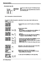
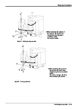
* Moving along an arc

* Moving along an arc

* Moving along an arc

* Moving along an arc
Assuming that the current position is on an 

Assuming that the current position is on an 

Assuming that the current position is on an 

Assuming that the current position is on an 
arc centering on the Z axis, the robot moves 

arc centering on the Z axis, the robot moves 

arc centering on the Z axis, the robot moves 

arc centering on the Z axis, the robot moves 
along that arc.

along that arc.

along that arc.

along that arc.
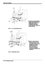
When the [MOVE] + [+Y (J2)] keys are 

When the [MOVE] + [+Y (J2)] keys are 

When the [MOVE] + [+Y (J2)] keys are 

When the [MOVE] + [+Y (J2)] keys are 
pressed, the robot will move along the arc in 

pressed, the robot will move along the arc in 

pressed, the robot will move along the arc in 

pressed, the robot will move along the arc in 
the plus direction.

the plus direction.

the plus direction.

the plus direction.
When the [MOVE] + [-Y (J2)] keys are 

When the [MOVE] + [-Y (J2)] keys are 

When the [MOVE] + [-Y (J2)] keys are 

When the [MOVE] + [-Y (J2)] keys are 
pressed, the robot will move in the minus 

pressed, the robot will move in the minus 

pressed, the robot will move in the minus 

pressed, the robot will move in the minus 
direction.

direction.

direction.

direction.

* Moving in the radial direction

* Moving in the radial direction

* Moving in the radial direction

* Moving in the radial direction
Assuming that the current position is on an 

Assuming that the current position is on an 

Assuming that the current position is on an 

Assuming that the current position is on an 
arc centering on the Z axis, the robot will 

arc centering on the Z axis, the robot will 

arc centering on the Z axis, the robot will 

arc centering on the Z axis, the robot will 
expand and contract in the radial direction.

expand and contract in the radial direction.

expand and contract in the radial direction.

expand and contract in the radial direction.
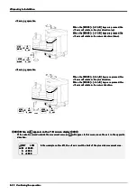
When the [MOVE] + [+X (J

1

)] keys are 

When the [MOVE] + [+X (J

1

)] keys are 

When the [MOVE] + [+X (J

1

)] keys are 

When the [MOVE] + [+X (J

1

)] keys are 

pressed, the robot will expand in the radial 

pressed, the robot will expand in the radial 

pressed, the robot will expand in the radial 

pressed, the robot will expand in the radial 
direction

direction

direction

direction
When the [MOVE] + [+X (J

1

)] keys are 

When the [MOVE] + [+X (J

1

)] keys are 

When the [MOVE] + [+X (J

1

)] keys are 

When the [MOVE] + [+X (J

1

)] keys are 

pressed, the robot will contract in the radial 

pressed, the robot will contract in the radial 

pressed, the robot will contract in the radial 

pressed, the robot will contract in the radial 
direction

direction

direction

direction

* Moving along the Z axis

* Moving along the Z axis

* Moving along the Z axis

* Moving along the Z axis
When the [MOVE] + [+Z (J3)] keys are 

When the [MOVE] + [+Z (J3)] keys are 

When the [MOVE] + [+Z (J3)] keys are 

When the [MOVE] + [+Z (J3)] keys are 
pressed, the robot will move along the Z axis 

pressed, the robot will move along the Z axis 

pressed, the robot will move along the Z axis 

pressed, the robot will move along the Z axis 
plus direction.

plus direction.

plus direction.

plus direction.
When the [MOVE] + [-Z (J3)] keys are 

When the [MOVE] + [-Z (J3)] keys are 

When the [MOVE] + [-Z (J3)] keys are 

When the [MOVE] + [-Z (J3)] keys are 
pressed, the robot will move along the minus 

pressed, the robot will move along the minus 

pressed, the robot will move along the minus 

pressed, the robot will move along the minus 
direction.

direction.

direction.

direction.

CYLNDER    LOW

CYLNDER    LOW

CYLNDER    LOW

CYLNDER    LOW
   R   +

1

34.50

   R   +

1

34.50

   R   +

1

34.50

   R   +

1

34.50

   T   +220.00

   T   +220.00

   T   +220.00

   T   +220.00
   Z   +280.00

   Z   +280.00

   Z   +280.00

   Z   +280.00

Select the cylindrical jog mode

Select the cylindrical jog mode

Select the cylindrical jog mode

Select the cylindrical jog mode

CYLNDER    LOW

CYLNDER    LOW

CYLNDER    LOW

CYLNDER    LOW
   R   +

1

34.50

   R   +

1

34.50

   R   +

1

34.50

   R   +

1

34.50

   T   +220.00

   T   +220.00

   T   +220.00

   T   +220.00
   Z   +280.00

   Z   +280.00

   Z   +280.00

   Z   +280.00

Set the jog speed

Set the jog speed

Set the jog speed

Set the jog speed

Cylindrical jog mode                              

Cylindrical jog mode                              

Cylindrical jog mode                              

Cylindrical jog mode                              

STEP

STEP

STEP

STEP

MOVE

MOVE

MOVE

MOVE

XYZ

XYZ

XYZ

XYZ

$":

$":

$":

$":

Set the speed                                         

Set the speed                                         

Set the speed                                         

Set the speed                                         

STEP

STEP

STEP

STEP

MOVE

MOVE

MOVE

MOVE

FORWD

FORWD

FORWD

FORWD

BACKWD

BACKWD

BACKWD

BACKWD

+X

 axis


+Y

 axis


+Z

 axis


J4

J4

J4

J4

Arc

Arc

Arc

Arc

 Radius

 Radius

 Radius

 Radius

Vertical

Vertical

Vertical

Vertical

Moving along an arc centering on the Z axis

Moving along an arc centering on the Z axis

Moving along an arc centering on the Z axis

Moving along an arc centering on the Z axis

The direction of the

The direction of the

The direction of the

The direction of the

 frange will not move.

 frange will not move.

 frange will not move.

 frange will not move.

STEP

STEP

STEP

STEP

MOVE

MOVE

MOVE

MOVE

+Z

+Z

+Z

+Z

(J3)

(J3)

(J3)

(J3)

8

88

8    

   ,@

\

   ,@

\

   ,@

\

   ,@

\

STEP

STEP

STEP

STEP

MOVE

MOVE

MOVE

MOVE

-Z

-Z

-Z

-Z

(J3)

(J3)

(J3)

(J3)

3

33

3    


JKL

JKL

JKL

JKL

STEP

STEP

STEP

STEP

MOVE

MOVE

MOVE

MOVE

-Y

-Y

-Y

-Y

(J2)

(J2)

(J2)

(J2)

4   

4   

4   

4   

MNO

MNO

MNO

MNO

+X

+X

+X

+X

(J

1

)

(J

1

)

(J

1

)

(J

1

)


’; ^


’; ^


’; ^


’; ^

STEP

STEP

STEP

STEP

MOVE

MOVE

MOVE

MOVE

+Y

+Y

+Y

+Y

(J2)

(J2)

(J2)

(J2)

9    

9    

9    

9    

&<>

&<>

&<>

&<>

STEP

STEP

STEP

STEP

MOVE

MOVE

MOVE

MOVE

STEP

STEP

STEP

STEP

MOVE

MOVE

MOVE

MOVE

-X

-X

-X

-X

(J

1

)

(J

1

)

(J

1

)

(J

1

)

SPACE

SPACE

SPACE

SPACE

PQR

PQR

PQR

PQR

Summary of Contents for RP-1AH Series

Page 1: ...MITSUBISHI Mitsubishi Industrial Robot RP 1AH 3AH 5AHSeries INSTRUCTIONMANUAL ROBOT ARM SETUP MAINTENANCE BFP A8111 A...

Page 2: ...tc This also applies to maintenance work with the power source turned ON ON ON ON Indication of teaching work in progress Indication of teaching work in progress Indication of teaching work in progres...

Page 3: ...bot or to incorrect operation lead to operators approaching the robot or to incorrect operation lead to operators approaching the robot or to incorrect operation When carrying out teaching work in the...

Page 4: ...ric shock accidents Failure to do so could lead to electric shock accidents Failure to do so could lead to electric shock accidents Failure to do so could lead to electric shock accidents Note1 NV 30...

Page 5: ...11 BFP A8111Z a Z a Z a Z a Error in writing correction Error in writing correction Error in writing correction Error in writing correction 2000 06 30 2000 06 30 2000 06 30 2000 06 30 BFP A8111 BFP A8...

Page 6: ...ior consent from No part of this manual may be reproduced by any means or in any form without prior consent from No part of this manual may be reproduced by any means or in any form without prior cons...

Page 7: ...2 18 2 18 1 1 1 1 Joint jog operation Joint jog operation Joint jog operation Joint jog operation 2 21 2 21 2 21 2 21 2 2 2 2 XYZ jog operation XYZ jog operation XYZ jog operation XYZ jog operation 2...

Page 8: ...the backup battery Replacing the backup battery Replacing the backup battery 5 51 5 51 5 51 5 51 1 1 1 1 Replacing the robot arm battery Replacing the robot arm battery Replacing the robot arm batter...

Page 9: ...t arm unpacking transportation Explains the procedures required to operate the robot arm unpacking transportation Explains the procedures required to operate the robot arm unpacking transportation Exp...

Page 10: ...the robot to safely use the robot Precaution indicating cases where operator could be subject to injury or Precaution indicating cases where operator could be subject to injury or Precaution indicatin...

Page 11: ...rce turned ON Setting of emergency stop switch Setting of emergency stop switch Setting of emergency stop switch Setting of emergency stop switch During teaching work place a sign indicating that teac...

Page 12: ...e could Indicate the operation state during robot operation Failure to indicate the state could lead to operators approaching the robot or to incorrect operation lead to operators approaching the robo...

Page 13: ...AH AH AH 5 5 5 5AHC SB AHC SB AHC SB AHC SB 1 1 1 1 Robot arm Robot arm Robot arm Robot arm RP 1AH 1AHC SB RP 1AH 1AHC SB RP 1AH 1AHC SB RP 1AH 1AHC SB RP 3AH 3AHC SB RP 3AH 3AHC SB RP 3AH 3AHC SB RP...

Page 14: ...ard packaging Refer to Table 2 1 and unpack the robot Handle The robot is shipped from the factory in cardboard packaging Refer to Table 2 1 and unpack the robot Handle The robot is shipped from the f...

Page 15: ...r impact when transferring the robot to the installation place 3 Avoid applying vibration or impact when transferring the robot to the installation place 4 Remove the transportation jigs A and B after...

Page 16: ...places Spring washer Small plain washer M8 40 hexagon socket bolt 4 places RP 3AH 3AHC SB 5AH 5AHC SB 4 7 installation hole Bottom side of base Bottom side of base Bottom side of base Bottom side of b...

Page 17: ...ould be or more If the installation surface is 2 The surface roughness of the installation surface should be or more If the installation surface is 2 The surface roughness of the installation surface...

Page 18: ...nd controller as possible close to the robot arm and controller as possible close to the robot arm and controller as possible and the length of the grounding wire should be and the length of the groun...

Page 19: ...controller side and robot arm The machine cable connectors are dedicated for the controller side and robot arm The machine cable connectors are dedicated for the controller side and robot arm side so...

Page 20: ...control power ON the control power ON the control power ON 1 Installing with the control power OFF 1 Installing with the control power OFF 1 Installing with the control power OFF 1 Installing with th...

Page 21: ...ned OFF Always install remove the cover with the controller control power turned OFF Always install remove the cover with the controller control power turned OFF Failure to do so could lead to physica...

Page 22: ...de selection key switch on the front of the controller to TEACH and then set the T B ENABLE DISABLE switch to ENABLE then set the T B ENABLE DISABLE switch to ENABLE then set the T B ENABLE DISABLE sw...

Page 23: ...power The screen for 4 Press the 1 and INP keys to turn OFF the servo power The screen for inputting the origin data will appear inputting the origin data will appear inputting the origin data will a...

Page 24: ...e 9 key input 9 V S29 will appear at the D data on the teaching pendant screen V S29 will appear at the D data on the teaching pendant screen V S29 will appear at the D data on the teaching pendant sc...

Page 25: ...the and keys Press the and keys Press the and keys Press the and keys Inputting characters Inputting characters Inputting characters Inputting characters Hold down the CHAR key and press the key with...

Page 26: ...obot and that there are no obstacles such as tools in the robot operation range range range range To immediately stop the robot release the deadman switch on the back of the T B To immediately stop th...

Page 27: ...t moves straight along the orthogonal straight along the orthogonal straight along the orthogonal straight along the orthogonal coordinate system coordinate system coordinate system coordinate system...

Page 28: ...At this time the end axis changes At this time the end axis changes At this time the end axis changes At this time the end axis position will change position will change position will change position...

Page 29: ...When the MOVE Y J2 keys are pressed the When the MOVE Y J2 keys are pressed the When the MOVE Y J2 keys are pressed the When the MOVE Y J2 keys are pressed the J2 axis will rotate in the plus directio...

Page 30: ...direction J4 axis will rotate in the minus direction axis axis axis axis axis axis axis axis J3 axis jog operation J3 axis jog operation J3 axis jog operation J3 axis jog operation J4 axis jog operat...

Page 31: ...J3 keys are When the MOVE Z J3 keys are When the MOVE Z J3 keys are pressed the robot will move along the Z axis pressed the robot will move along the Z axis pressed the robot will move along the Z a...

Page 32: ...in the same direction is not possible JOINT LOW JOINT LOW JOINT LOW JOINT LOW X X 360 00 X X 360 00 X X 360 00 X X 360 00 Y 280 00 Y 280 00 Y 280 00 Y 280 00 Z 170 00 Z 170 00 Z 170 00 Z 170 00 X X X...

Page 33: ...direction direction Moving along the Z axis Moving along the Z axis Moving along the Z axis Moving along the Z axis When the MOVE Z J3 keys are When the MOVE Z J3 keys are When the MOVE Z J3 keys are...

Page 34: ...ple on the left further linear movement in the same direction is not possible TOOL LOW TOOL LOW TOOL LOW TOOL LOW X 360 00 X 360 00 X 360 00 X 360 00 280 00 280 00 280 00 280 00 170 00 170 00 170 00 1...

Page 35: ...ection plus direction plus direction plus direction When the MOVE Z J3 keys are When the MOVE Z J3 keys are When the MOVE Z J3 keys are When the MOVE Z J3 keys are pressed the robot will move along th...

Page 36: ...n the MOVE C J6 keys are When the MOVE C J6 keys are When the MOVE C J6 keys are When the MOVE C J6 keys are pressed the Z axis will rotate in the minus pressed the Z axis will rotate in the minus pre...

Page 37: ...ssuming that the current position is on an Assuming that the current position is on an arc centering on the Z axis the robot will arc centering on the Z axis the robot will arc centering on the Z axis...

Page 38: ...J6 keys are When the MOVE C J6 keys are When the MOVE C J6 keys are When the MOVE C J6 keys are pressed the Z axis will rotate in the minus pressed the Z axis will rotate in the minus pressed the Z ax...

Page 39: ...the plate 3 onto which the solenoid valve is installed plate 3 onto which the solenoid valve is installed plate 3 onto which the solenoid valve is installed plate 3 onto which the solenoid valve is in...

Page 40: ...nstalling the solenoid valve set Installing the solenoid valve set 1A VD04 RP 1A VD04 RP 1A VD04 RP 1A VD04 RP 1A VD04 1A VD04 1A VD04 1A VD04E E E E PR PR PR PR 3 3 3 3Installing the option devices I...

Page 41: ...The basic operations from creating the program to automatic operation are explained in section 4 Basic The basic operations from creating the program to automatic operation are explained in section 4...

Page 42: ...4 34 4 34 4 34 4 34 4 4 4 4Basic operations Basic operations Basic operations Basic operations...

Page 43: ...i i i i l l l l y y y y i i i i n n n n s s s s p p p p e e e e c c c c t t t t i i i i o o o o n n n n Monthly inspection Monthly inspection Monthly inspection Monthly inspection Monthly inspection M...

Page 44: ...obstacles on the robot and controller cover and controller cover and controller cover and controller cover Replace with a new part or take remedial measures Replace with a new part or take remedial m...

Page 45: ...r Check and eliminate the cause Check and eliminate the cause Check and eliminate the cause Check and eliminate the cause If the cables are severely damaged contact the If the cables are severely dama...

Page 46: ...nspection are described in The maintenance parts etc required for the user to carry out maintenance and inspection are described in The maintenance parts etc required for the user to carry out mainten...

Page 47: ...J2 axis motor 4 As with the J1 axis non excitation magnetic brakes are mounted on the J2 axis motor 4 3 J3 axis 3 J3 axis 3 J3 axis 3 J3 axis The rotation of the J3 axis motor 7 installed on the base...

Page 48: ...M4 4 Set screw with hole RP 3AH 5AH 2 M4 4 RP 1AH Set screw with hole Cover installation screw list Cover installation screw list Cover installation screw list Cover installation screw list No No No...

Page 49: ...t appear when it is used with being damaged may not appear when it is used with being damaged may not appear when it is used with being damaged In the case of clean type robot RP 1AHC SB 3AHC SB 5AHC...

Page 50: ...e timing belt must be replaced in the following cases 1 Timing belt replacement period 1 Timing belt replacement period 1 Timing belt replacement period 1 Timing belt replacement period The timing bel...

Page 51: ...a in the drawing the belt will be tensed and when moved in the 4 When moved in the direction of arrow a in the drawing the belt will be tensed and when moved in the 4 When moved in the direction of ar...

Page 52: ...on of the arrow in the drawing 3 While checking the timing belt 2 tension degree move the idler 5 in the direction of the arrow in the drawing 3 While checking the timing belt 2 tension degree move th...

Page 53: ...ket screw 2 Timing belt J4 4 Timing pulley b a No 1 arm L 7 Installation screw 7 Installation screw 6 Pulley housing 9 Shaft 6 Pulley housing 8 M3 screw hole 8 M3 screw hole a Inspecting adjusting and...

Page 54: ...ting the tension Doing so could cause the machine system s origin to pulley teeth engagement when adjusting the tension Doing so could cause the machine system s origin to deviate deviate deviate devi...

Page 55: ...moved in the 4 When moved in the direction of arrow a in the drawing the belt will be tensed and when moved in the 4 When moved in the direction of arrow a in the drawing the belt will be tensed and w...

Page 56: ...the belt tension side will vibrate The adjustment value for the tension degree is shown in Fig 5 9 The adjustment value for the tension degree is shown in Fig 5 9 The adjustment value for the tension...

Page 57: ...e grease does not run out The numbers in the above table correspond to the supply positions in Fig 5 10 The numbers in the above table correspond to the supply positions in Fig 5 10 The numbers in the...

Page 58: ...rease on the exposed ball screw spline and then paint the grease shown in the Table 5 3 paint the grease shown in the Table 5 3 paint the grease shown in the Table 5 3 paint the grease shown in the Ta...

Page 59: ...e robot arm and controller as soon as possible Lithium batteries type A6BAT occurs replace all batteries in the robot arm and controller as soon as possible Lithium batteries type A6BAT and ER6 are us...

Page 60: ...e time Refer to the Always carry out this step after replacing the battery and initialize the battery usage time Refer to the Always carry out this step after replacing the battery and initialize the...

Page 61: ...ease Harmonic grease B 2 Harmonic grease B 2 Harmonic grease B 2 Harmonic grease B 2 An needed An needed An needed An needed Reduction gears of J1 J2 axis Reduction gears of J1 J2 axis Reduction gears...

Page 62: ...oulder cover Shoulder cover Shoulder cover Shoulder cover Mitsubishi Electric Mitsubishi Electric Mitsubishi Electric Mitsubishi Electric 2 2 2 2 1 1 1 1 Shoulder cover Shoulder cover Shoulder cover S...

Page 63: ...re to column of the BRAKE which the brakes are to column of the BRAKE which the brakes are to column of the BRAKE which the brakes are to be released and press the X key while holding be released and...

Page 64: ...this condition with the fixing bolts under this condition with the fixing bolts under this condition with the fixing bolts under this condition d Release the brakes of all axis and take the end d Rele...

Page 65: ...e set origin will be set origin will be set This completes the setting of the origin with the jig method This completes the setting of the origin with the jig method This completes the setting of the...

Page 66: ...rded in the user designated origin parameter USRORG 3 Input the value recorded in the user designated origin parameter USRORG 3 Input the value recorded in the user designated origin parameter USRORG...

Page 67: ...Replacing the backup battery on page 51 and remove the connector box cover Refer to 5 3 5 Replacing the backup battery on page 51 and remove the connector box cover Refer to 5 3 5 Replacing the backu...

Page 68: ...0 60 60 60 Resetting the origin Resetting the origin Resetting the origin Resetting the origin 5 5 5 5Maintenance and Inspection Maintenance and Inspection Maintenance and Inspection Maintenance and I...

Page 69: ...cification JUL 2000 MEE Printed in Japan on recycled paper Specifications are subject to change without notice s are subject to change without notice s are subject to change without notice s are subje...

Reviews: