3 Controller
Names of each part 3-33
⑫
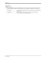
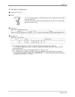
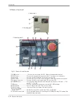
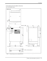
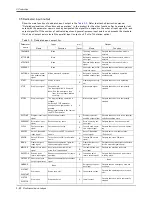
MODE key switch............................. This changes the robot's operation mode.
AUTOMATIC................................operations from the controller or external equipment are valid. Operations for
which the operation mode must be at the external device or T/B are not possible. It
is necessary to set the parameter for the rights of operation to connection
between the operation panel and external equipment. For details, please refer to
"INSTRUCTION MANUAL/Detailed explanations of functions and operations" of
the separate volume.
MANUAL........................................When the T/B is valid, only operations from the T/B are valid. Operations for which
the operation mode must be at the external device or controller are not possible.
⑬
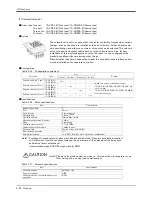
UP/DOWN button............................ This scrolls up or down the details displayed on the "STATUS. NUMBER" display panel.
⑭ Interface cover ...........................USB interface and battery are mounted.
⑮ RS-232 connector
...................... This is an RS-232C specification connector for connecting the personal computer.
⑯
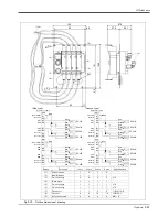
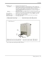
Power cable clamp .......................... Fix the primary power cable.
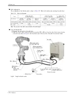
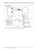
1) Machine cable (for motor power) ................................. Connects to the robot arm base. (CN1 connector)
2) Machine cable (for motor signal).................................. Connects to the robot arm base. (CN2 connector)
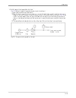
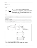
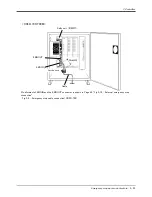
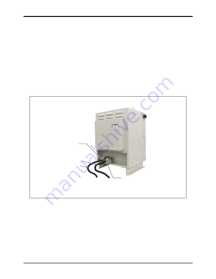
Fig.3-2 : Names of each part (Rear side CR3D-700 series)
CN2
CN1
①
②
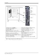
< CR3D-700 series >
① Machine cable connector (motor power)(CN1)........... Connects to the robot arm base. (CN1 connector)
② Machine cable connector (motor signal)(CN2)............ Connects to the robot arm base. (CN2 connector)

