background image


2Unpacking to Installation


Confirming the operation

   2-27

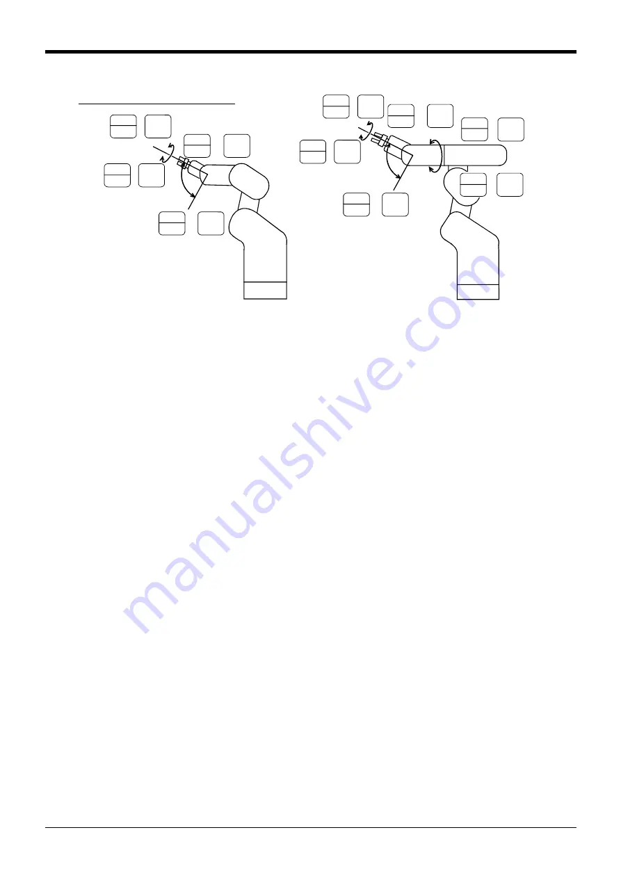
When the [MOVE] + [+A (J4)] keys are pressed, the J4-axis will rotate in the plus direction.

When the [MOVE] + [-A (J4)] keys are pressed, Rotate in the minus direction. (6-axis type only)

When the [MOVE] + [+B (J5)] keys are pressed, the J5-axis will rotate in the plus direction.

When the [MOVE] + [-B (J5)] keys are pressed, Rotate in the minus direction.

When the [MOVE] + [+C (J6)] keys are pressed, the J6-axis will rotate in the plus direction.

When the [MOVE] + [-C (J6)] keys are pressed, Rotate in the minus direction.


1   

DEF

- B

(J5)

STEP

MOVE


5


 STU

+ C

(J6)

STEP

MOVE


5


 STU

+ C

(J6)

STEP

MOVE


J5 axis

J6 axis

J4 axis

5-axis type

J5 axis

J6 axis


1


 DEF

- B

(J5)


STEP

MOVE


0


ABC

- C

(J6)

STEP

MOVE


STEP

MOVE  


0


ABC

- C

(J6)

STEP

MOVE


6


VWX

B

(J5)

7

A

(J4)

STEP

MOVE


 YZ_


6

VWX

B

(J5)

STEP

MOVE


2

A

(J4)

STEP

MOVE

 GHI

6-axis type

* The flange position changes.

Interpolate the joint, taking care not to change the 
control point. operation.

Changing the flange surface posture

Summary of Contents for RV-2AJ

Page 1: ...MITSUBISHI Mitsubishi Industrial Robot RV 2A 3AJ INSTRUCTION MANUAL ROBOT ARM SETUP MAINTENANCE BFP A8183 B...

Page 2: ...s on the start switch etc This also applies to maintenance work with the power source turned ON Indication of teaching work in progress Provide a fence or enclosure during operation to prevent contact...

Page 3: ...obot operation Failure to indicate the state could lead to operators approaching the robot or to incorrect operation When carrying out teaching work in the robot s movement range always secure the pri...

Page 4: ...ector of the input power supply voltage of the controller if the type which more than one power supply voltage can be used Then connect the power supply Failure to do so could lead to electric shock a...

Page 5: ...No Revision Details 2001 09 11 BFP A8183Z First print 2001 09 25 BFP A8183 Formal style 2001 12 06 BFP A8183 A The explanation of the attached part of packing was added Error in writing correction 20...

Page 6: ...out prior consent from Mitsubishi The details of this manual are subject to change without notice An effort has been made to make full descriptions in this manual However if any discrepancies or uncle...

Page 7: ...the shoulder cover B 2 16 2 4 Confirming the operation 2 17 1 JOINT jog operation 2 20 2 XYZ jog operation 2 22 3 TOOL jog operation 2 24 4 3 axis XYZ jog operation 2 26 5 CYLNDER jog operation 2 28...

Page 8: ...eal section lubrication method for only clean specification 5 60 5 3 6 How to lubricate the spring shaft area 5 62 5 3 7 Replacing the backup battery 5 63 1 Replacing the robot arm battery 5 63 5 4 Ma...

Page 9: ...ogy when incorporating the robot are also explained Explains the procedures required to operate the robot arm unpacking transportation installation confirmation of operation and the maintenance and in...

Page 10: ...s if handling is mistaken Always observe these precautions to safely use the robot Precaution indicating cases where operator could be subject to injury or physical damage could occur if handling is m...

Page 11: ...ng work This also applies to maintenance work with the power source turned ON Setting of emergency stop switch During teaching work place a sign indicating that teaching work is in progress on the sta...

Page 12: ...accidents Indicate the operation state during robot operation Failure to indicate the state could lead to operators approaching the robot or to incorrect operation When carrying out teaching work in...

Page 13: ...refer to the separate Standard Specifications Table 2 1 Standard configuration Note The number 3 6 are in the plastic bag of the robot arm attachment No Part name Type Qty Remarks 1 Robot arm RV 2A RV...

Page 14: ...ox gently down so that the unpacking instructions on the top cover faces down 3 Pull the cushioning material A and B which encloses the robot arm out of the cardboard box as shown in Fig 2 1 3 4 Remov...

Page 15: ...nsporting the robot use a cart Carrying the robot arm by its grips should be limited to putting it on a cart or stand or to reposition it 4 When transporting the robot arm use an assistant and make it...

Page 16: ...th the table will be poor and positional deviation could occur when the robot moves 4 When installing use a common table to prevent the position of the devices and jigs subject to robot work from devi...

Page 17: ...ding point should be as close to the robot arm and controller as possi ble and the length of the grounding wire should be short Fig 2 4 Grounding methods 2 Grounding procedures 1 Prepare the grounding...

Page 18: ...onding connector on the controller The machine cable connectors are dedicated for the controller side and robot arm side so take special care when connecting If connected incorrectly the connector pin...

Page 19: ...r OFF Refer to the separate Controller setup basic operation and maintenance for details on installing the teaching pendant with the control power ON 1 Installing with the control power OFF 1 Confirm...

Page 20: ...does not have the J4 axis Fig 2 8 Origin data label an example Always install remove the cover with the controller control power turned OFF Failure to do so could lead to physical damage or personal...

Page 21: ...E DISABLE ENABLE EMG STOP DISABLE ENABLE Operating from the T B Always set the MODE switch mode selection key switch on the front of the controller to TEACH and then set the T B ENABLE DISABLE switch...

Page 22: ...the servo power will appear 4 Press the 1 and INP keys to turn OFF the servo power The screen for inputting the origin data will appear MENU 1 TEACH 2 RUN 3 FILE 4 MONI 5 MAINT 6 SET DATA D 000000 1 0...

Page 23: ...se the CHAR key and press the 2 key input 2 and then the 9 key input 9 V S29 will appear at the D data on the teaching pendant screen 3 Press the key and move the cursor to the J1 input position 4 Inp...

Page 24: ...f incorrect operations or to physical damage or personal injury Moving the cursor Press the and keys Inputting characters Hold down the CHAR key and press the key with the character to be input on the...

Page 25: ...tacles such as tools in the robot operation range To immediately stop the robot release the deadman switch on the back of the T B The servo power will turn OFF and the robot will stop The robot will a...

Page 26: ...base coor dinate system Also while maintaining the flange surface position the flange surface posture changes 6 axis type X Z Control point T o o l l e n g t h Y Z X Y T o o l l e n g t h 5 axis type...

Page 27: ...Also the flange surface posture changes The flange surface position changes at this time 5 axis type X Y Z Z T o o l l e n g t h Redius Vertical Control point Arc T o o l l e n g t h 6 axis type Rediu...

Page 28: ...ction When the MOVE Y J2 keys are pressed the J2 axis will rotate in the plus direction When the MOVE Y J2 keys are pressed Rotate in the minus direction JOINT LOW J1 34 50 J2 20 00 J3 80 00 Select th...

Page 29: ...When the MOVE C J6 keys are pressed Rotate in the minus direction 6 axis type 5 axis type STEP MOVE 3 JKL Z J3 STEP MOVE 8 Z J3 STEP MOVE 3 JKL Z J3 STEP MOVE 8 Z J3 J3 axis J3 axis J3 axis jog opera...

Page 30: ...e X Y Z LOW X 134 50 Y 220 00 Z 280 00 Set the jog speed XYZ jog mode STEP MOVE XYZ Set the speed STEP MOVE FORWD BACKWD 6 axis type X Y Z X Y Z Z STEP MOVE 4 MNO Y J2 STEP MOVE 3 JKL Z J3 STEP MOVE X...

Page 31: ...ressed 6 axis type Rotate in the minus direction 5 axis type There is no operation 6 axis type 5 axis type X Y Z STEP MOVE 0 ABC C J6 7 YZ_ A J4 STEP MOVE 2 GHI A J4 STEP MOVE X Z Control point T o o...

Page 32: ...he MOVE Z J3 keys are pressed the robot will move along the Z axis plus direction of the tool coordinate system When the MOVE Z J3 keys are pressed Move along the minus direction TOOL LOW X 134 50 Y 2...

Page 33: ...eration When an X appears on the T B screen display If the robot is moved outside the movement area with any of the axes an X will appear In this case move the axis in the opposite direction In the ex...

Page 34: ...are pressed Move along the minus direction XYZ456 LOW X 134 50 Y 220 00 Z 280 00 Select the 3 axis XYZ jog mode XYZ456 LOW X 134 50 Y 220 00 Z 280 00 Set the jog speed 3 axis XYZ jog mode STEP MOVE X...

Page 35: ...ion When the MOVE C J6 keys are pressed the J6 axis will rotate in the plus direction When the MOVE C J6 keys are pressed Rotate in the minus direction 1 DEF B J5 STEP MOVE 5 STU C J6 STEP MOVE 5 STU...

Page 36: ...MOVE X J1 keys are pressed the robot will expand in the radial direction When the MOVE X J1 keys are pressed Contract in the radial direction When the MOVE Z J3 keys are pressed the robot will move a...

Page 37: ...rection 5 axis type There is no operation When the MOVE C J6 keys are pressed 6 axis type The Z axis will rotate in the plus direction 5 axis type There is no operation When the MOVE C J6 keys are pre...

Page 38: ...2 30 Confirming the operation 2Unpacking to Installation...

Page 39: ...olenoid valve connector connection procedures The installation procedures are as follow This work must be carried out with the controller power turned OFF 1 Remove the two M3x6 screws 2 and the two M3...

Page 40: ...rotruding from the primary solenoid valve 6 to the connector GR1 Connect the GR2 plug protruding from the primary solenoid valve 6 to the connector GR2 If you are using double type valves 1E VD02 VD02...

Page 41: ...the secondary solenoid valve 10 Connect the hose marked 4 to port B 12 on the secondary solenoid valve 10 6 Connect the GR1 plug protruding from the primary solenoid valve 6 to the connector GR1 Conne...

Page 42: ...in Table 3 2 for single type valves hand 2 is not applicable Table 3 2 Solenoid valve ports and hoses Connection table for couplings and hand ports for the RV 2AM 3AJM Hand Hand port Forearm coupling...

Page 43: ...and 1E HP01 1E HP01E 1 Hand input cable with pneumatic coupling 2 Pneumatic hand interface 2A RZ365 375 1 Interface board Install on the controller 3 Solenoid valve set 1E VD01 1E VD01E 1 Comes with t...

Page 44: ...he parameters For the pneumatic hand 1E HP01 1E HP01E the tool data is 107mm Refer to separate manual CR1 CR2 CR4 CR7 CR8 Controller INSTRUCTION MANUAL Detailed explanations of functions and operation...

Page 45: ...Configurations for the motorized hand set Number Part name Model type Quantity Notes 1 Motorozed hand 1A HM01 1 2 Motorozed hand curl cable 1E GHCD 1 1 3 Motorozed hand interface 2A RZ364 1 Install o...

Page 46: ...when the servo is OFF If the axis is rotated by more than operation range when the servo is ON an encoder alarm occur 3 3 2 Installation the motorized interface Refer to the separate CR1 Controller In...

Page 47: ...r to section 3 1Installing the solenoid valve set 1E VD01 VD01E VD02 VD02E 4 Table 3 1 on page 32 for the connection methods 3 5 Installing the hand input cable 1E HC15C and hand curl tube 1E ST040 C...

Page 48: ...3 40 Installing the hand input cable 1E HC15C and hand curl tube 1E ST040 C 3Installing the option devices...

Page 49: ...41 4 Basic operations The basic operations from creating the program to automatic operation are explained in section 4 Basic operations in the From Controller Setup to Maintenance manual Refer that m...

Page 50: ...4 42 4Basic operations...

Page 51: ...e following inspection items every three months estimated at 500 Hr operation hours Fig 5 1 Inspection schedule Hr Daily inspection Monthly inspection Monthly inspection Hr Monthly inspection 3 month...

Page 52: ...connect 6 Are there any cracks foreign contamination or obstacles on the robot and controller cover Replace with a new part or take remedial measures 7 Is any grease leaking from the robot arm Visual...

Page 53: ...aged contact the Mitsubishi Service Department 4 It runs out of grease on the spring shaft for J2 axis Refer to 5 3 6How to lubricate the spring shaft area on page 62 and lublicate it 3 month inspecti...

Page 54: ...the 6 axis type robot arm in Fig 5 3 Each part is as shown below 1 The J1 axis rotation is driven by the J1 axis motor 1 and reduction gears 2 arranged in the shoulder Non excitation magnetic brakes...

Page 55: ...J1 axis motor 2 J1 axis re duction gear 5 J3 axis motor 6 J3 axis reduction gear 3 J2 axis motor 4 J2 axis reduction gear Elbow block Upper arm Shoulder Forearm Wrist housing 1 J1 axis motor 5 J3 axis...

Page 56: ...o 1 arm cover L 2 Shoulder cover R 4 Shoulder cover B 1 Shoulder cover L 3 Shoulder cover F a a c a b b b c a b b b a c a a c a a a a a a a Screw driver a 15 Elbow bushing Rear of elbow cover 14 Wrist...

Page 57: ...remove due to the robot posture In this case change the robot posture with jog operation and then remove the cover 4 When attaching the cover after maintenance and inspection use the detaching procedu...

Page 58: ...irmed during the periodic inspection The timing belt must be replaced in the following cases 1 Timing belt replacement period The timing belt life is greatly affected by the robot working conditions s...

Page 59: ...ome off the timing pulleys 4 and 5 or if the belt and pulley teeth engagement is deviated the machine system s origin will deviate 6 After adjusting securely tighten the four motor installation bolts...

Page 60: ...a degree that elasticity is felt when the belt is pressed with the thumb If the belt tension is too weak the belt loosening side will vibrate On the other hand if the belt tension is too strong a sha...

Page 61: ...e dust sticking on the inside of cover with dry cloth or with alcohol Take care not to damage the sponge packing attached on the No 2 arm cover U L at this time 3 Wipe the dust sticking on the inside...

Page 62: ...J1 axis grease charge port 5 J5 axis grease charge port 6 J6 axis grease charge port 2 J2 axis grease charge port 7 Spring shaft In the shoulder cover L 3 J3 axis grease charge port 4 J4 axis grease...

Page 63: ...will fluctuate so determine the time according to the state so that the grease does not run out The numbers in the Table 5 5 correspond to the supply positions in Fig 5 9 No Parts to be lubricated Oil...

Page 64: ...purging bolt 1 Take care not to lose the washer with seal at this time There is no air purging bolt except for the clean specification 3 Lubricate the grease shown in the Table 5 5 from grease nipple...

Page 65: ...is lubrication method J3 axis lubrication method Fig 5 12 shows the procedures for J3 axis lubrication method 1 Remove the shoulder cover F B R and No 2 arm cover R 2 Remove the air purging bolt 1 Tak...

Page 66: ...This completes the J4 axis lubrication Fig 5 13 J4 axis lubrication method J5 axis lubrication method Fig 5 14 shows the procedures for J5 axis lubrication method 1 Remove the No 2 arm cover U 2 In t...

Page 67: ...clean specification 3 Lubricate the grease shown in the Table 5 5 from grease nipple 2 4 In the case of clean specification tighten the air purging bolt 1 which removed with the above step 2 Do not fo...

Page 68: ...o the 5 3 2Installing removing the cover on page 48 and remove the necessary covers 1 Remove the elbow cover U 2 Make marks on the seal ring 1 and ring guide 2 with a felt tip pen so that the position...

Page 69: ...s not adhered 5 Apply grease BARRIERTA IMI V onto the surface that the ring 2 oil seal contacts using a brush etc 6 Return the ring 2 to the original position Match the surface that the sponge is atta...

Page 70: ...case thereby compensating for the gravity by the spring force Depending on the conditions under which the robot is used wear may occur due to lack of lubrication in the spring shaft areas If wear is...

Page 71: ...arm and controller as soon as possible Lithium batteries type A6BAT and ER6 are used in both the controller and robot arm The procedure of battery replacement of robot arm is explained below 1 Replaci...

Page 72: ...r cover B from the robot Refer to 5 3 2Installing removing the cover on page 48 5 Remove the installation screws 5 in section A of the robot arm and remove the battery cover 4 6 The battery holder is...

Page 73: ...A IMI V J4 J5 J6 of clean specification An needed 4 Shell Alvania Grease No 2 Spring shaft in base An needed 5 Lithium battery A6BAT In battery cover 5 axis type 4 6 axis type 5 No Part name Type Usag...

Page 74: ...opper method This origin posture is set by contacting each axis against the mechanical stopper The setting method is explained in 5 5 1Mechanical stopper method on page 67 3 Jig method The origin post...

Page 75: ...select the jig method Then press the 1 key and the INP key to turn the servo OFF When setting the origin all axes can be set or only random axes can be set The methods corresponding to the axes to be...

Page 76: ...data on the origin data seal J1 Designate the origin setting axis B J5 1 DEF C J6 0 ABC INP EXE Set the origin B J5 1 DEF MECHA SET ORIGIN OK 1 1 EXECUTE INP EXE Release the brakes B J5 1 DEF Move th...

Page 77: ...e posture If the T B X key or the deadman switch is released the brakes will be applied immediately 6 Press the key The cursor will move to SET AXIS 7 Designate the axis for which the origin is to be...

Page 78: ...by its own weight depending on the posture If the T B X key or the deadman switch is released the brakes will be applied immediately Releasing the brakes To release the brakes move the cursor to the B...

Page 79: ...NP EXE Move the cursor RPL MECHA 12345678 BRAKE 00100000 SET AXIS 00100000 ORIGIN NOT DEF MECHA 12345678 BRAKE 00100000 SET AXIS 00100000 ORIGIN COMPLETED Releasing the brakes To release the brakes mo...

Page 80: ...the J4 axis is rotated and then apply the brakes Then set the J4 axis origin For safety purposes the step for releasing the brakes must be carried out by two workers One worker must operate the T B a...

Page 81: ...INP EXE Move the cursor RPL MECHA 12345678 BRAKE 00010000 SET AXIS 00010000 ORIGIN NOT DEF MECHA 12345678 BRAKE 00010000 SET AXIS 00010000 ORIGIN COMPLETED Releasing the brakes To release the brakes m...

Page 82: ...eased the brakes will be applied immediately 6 Press the key The cursor will move to SET AXIS 7 Designate the axis for which the origin is to be set Set 1 for the 5 axis and set 0 for the other axes T...

Page 83: ...the brakes To release the brakes move the cursor to the BRAKE axis No with the or key The brakes can be released only for the axis for which a 1 is displayed on the screen If the brakes are not to be...

Page 84: ...s To release the brakes move the cursor to the BRAKE axis No with the or key The brakes can be released only for the axis for which a 1 is displayed on the screen If the brakes are not to be released...

Page 85: ...al J5 J3 J2 J1 Front of the robot J6 mark agrees J5 J3 J2 J1 J4 J6 mark agrees Front of the robot 5 axis type 6 axis type JIG 12345678 BRAKE 00000000 SET AXIS 11110000 ORIGIN NOT DEF Designate the ori...

Page 86: ...5 key on the Menu screen to select the Maintenance screen 2 Press the 4 key to select the Origin Setting screen 3 Press the 3 key to select the jig method Then press the 1 key and the INP key to turn...

Page 87: ...switch or T B X W key is released the brakes will be applied immediately 8 Set the robot posture with the brakes released Contact the calibration jig against the machined surface on the front and sid...

Page 88: ...Refer to 5 5 5Recording the origin data on page 84 in this manual and record the origin data on the origin data seal This completes the setting of the origin with the jig method JIG 12345678 BRAKE 11...

Page 89: ...position where it doesn t move by the gravity This position is left as a guideline to position all axes with jog operation when setting the origin again with this method 2 Enter the JOINT jog mode an...

Page 90: ...nd then the INP key The origin will be set This completes the setting of the origin with the user origin method Designate the origin setting axis USER 12345678 BRAKE 00000000 SET AXIS 11111100 ORIGIN...

Page 91: ...1 key and the INP key to turn the servo OFF The origin of each axis can be set in the same manner as described in 5 5 1Mechanical stopper method on page 67 2 J1 axis origin setting on page 68 and suc...

Page 92: ...Confirming the origin data label Remove the shoulder cover B Refer to 5 3 2Installing removing the cover on page 48 and remove the shoulder cover B 2 Confirming the origin data Confirm the value displ...

Page 93: ...on flags are shown below 1 RIGHT LEFT P is center of flange in comparison with the plane through the J1 axis vertical to the ground Q is center of J5 axis rotation in comparison with the plane through...

Page 94: ...IP 6 axis robot only This means in which side the J6 axis is in comparison with the plane through both the J4 and the J5 axis Fig 6 3 Configuration flag NONFLIP FLIP FLIP NON FLIP J4 axis Mechanical i...

Page 95: ...Japan on recycled paper Specifications are subject to change without notice HEAD OFFICE MITSUBISHI DENKI BLDG MARUNOUCHI TOKYO 100 8310 TELEX J24532 CABLE MELCO TOKYO NAGOYA WORKS 1 14 YADA MINAMI 5...

Reviews: