5-78
Resetting the origin
5Maintenance and Inspection
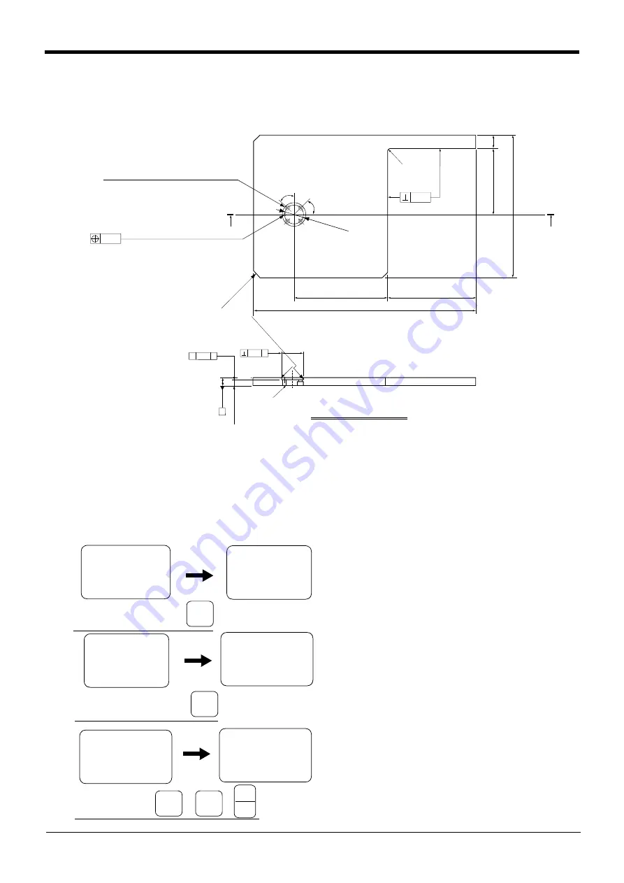
5.5.2 Jig method
The reference dimension drawing of the calibration jig (
1
E-INST) used with this method is shown in
This jig is the same option as the Mitsubishi RV-E, RV-EN, RV-4A/5AJ/3AL/4AJL Series.
Fig.5-20
: 1
E-INST (calibration jig) reference dimension drawing
The procedure of setting the origin with the calibration jig is shown below.
This operation is carried out with the teaching pendant. Set the [MODE] switch on the front of the controller to
"TEACH", and set the [ENABLE/DISABLE] switch on the teaching pendant to "ENABLE" to enable the teaching
pendant.
The following operation is carried out while lightly pressing the deadman switch on the teaching pendant.
1
) Press the [5] key on the Menu screen to select
the Maintenance screen.
2) Press the [4] key to select the Origin Setting
screen.
3) Press the [3] key to select the jig method. Then,
press the [
1
] key and the [INP] key to turn the
servo OFF.
0.04
C
1
C0
.5
φ
40H7
+0.025
0
×
×
0.04
×
〃
1
4
11
.7
2
±
0.
0
5
R0
.4
o
r le
ss
6.3a
6.3a
1
.6a
Reamer through A-A
0.05
R
1
0
A
A
26
7
1
22
±
0.
05
25
45
゜
φ
3
1
.5
1
74.94
±
0.05
1
63
4
1
0
0.02
(
The standard is in the
center of the
Φ
40H7
)
3-
C
1
0
φ5
H7
+0.0
1
2
0
reamer through
4-5.5 drill through
(equal circumference divisions)
φ11×
7 counterbore
(from rear surface)
6.3a
6.
3a
<MENU>
1.TEACH 2.RUN
3.FILE 4.MONI
5.MAINT 6.SET
<MAINT>
1.PARAM 2.INIT
3.BRAKE 4.ORIGIN
5.POWER
Select the maintenance screen
+C
(J6)
5
STU
<JIG>
SERVO OFF
OK ? (1)
1:EXECUTE
Select the Origin Setting screen
<MAINT>
1.PARAM 2.INIT
3.BRAKE 4.ORIGIN
5.POWER
<ORIGIN>
1.DATA 2.MECH
3.JIG
4.ABS
5.USER
-Y
(J2)
4
MNO
<ORIGIN>
1.DATA 2.MECH
3.JIG
4.ABS
5.USER
Select the jig method
-Z
(J3)
3
JKL
→
-B
(J5)
1
DEF
→
INP
EXE


