5Maintenance and Inspection
Resetting the origin
5-79
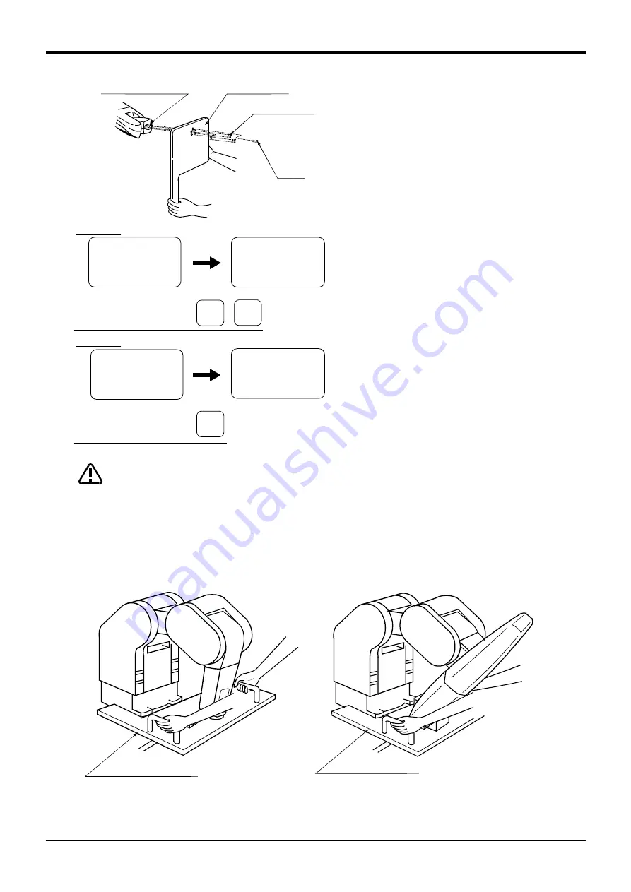
4) Install the calibration jig <
1
> on the mechanical
interface <2>, and insert the pin <4> to carry out
the positioning.
Tighten the bolt <3> in this state and securely fix
the jig. After fixing, remove the pin.
5) Designate the axis for which the brakes are to be
released.
Press the [
1
] key three times, the [0] key once,
and the [
1
] key once.
6) One worker must hold the calibration jig handle
or the robot arm.
7) While the other worker is holding down the dead
-
man switch on the teaching pendant, press the
[STEP/MOVE] and [+X] key. The brakes will be
released only while these keys are held down.
When the brakes are released, the robot arm could drop by its own weight depending
on the posture.
If the deadman switch or T/B [+X/+W] key is released, the brakes will be applied
immediately.
8) Set the robot posture with the brakes released.
Contact the calibration jig against the machined surface on the front and side of the base as bellow.
<JIG> 12345678
BRAKE
(00000000)
SET AXIS(00000000)
ORIGIN:NOT DEF
<JIG> 12345678
BRAKE
(11101000)
SET AXIS(11101000)
ORIGIN:NOT DEF
Designate the brakes release axis
5-axis type
-B
(J5)
1
DEF
-C
(J6)
0
ABC
・
<2> Mechanical interface
<2> Mechanical interface
<2> Mechanical interface
<2> Mechanical interface
<
1
> Calibration jig
<
1
> Calibration jig
<
1
> Calibration jig
<
1
> Calibration jig
<3> Bolt
<3> Bolt
<3> Bolt
<3> Bolt
<4> Pin
<4> Pin
<4> Pin
<4> Pin
(M5
×1
2: 4 bolts)
(M5
×1
2: 4 bolts)
(M5
×1
2: 4 bolts)
(M5
×1
2: 4 bolts)
Designate the brakes release axis
6-axis type
-B
(J5)
1
DEF
<JIG> 12345678
BRAKE
(00000000)
SET AXIS(00000000)
ORIGIN:NOT DEF
<JIG> 12345678
BRAKE
(11101100)
SET AXIS(11111100)
ORIGIN:NOT DEF
CAUTION
<1> Calibration jig
<1> Calibration jig
5-axis type
6-axis type


