2-11
Installation
2Unpacking to Installation
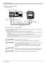
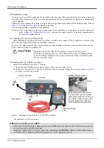
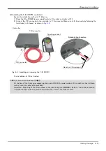
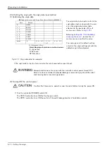
2.2.5 Connecting with the controller
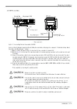
(1) CR750 controller
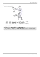
Fig.2-6 : Connecting the machine cables (CR750)
Carry out the following procedure after installing the controller referring to the separate "Controller Setup, Basic
Operation and Maintenance" manual.
1) Make sure that the power switch on the front of the controller is turned OFF.
2) Refer to
and connect the machine cable to its corresponding connector on the robot arm side and
controller.
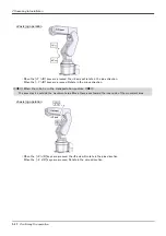
Connect the CN2 first at connection. Conversely, remove the CN1 first at removal.
After CN1 unites the key slot with each other's connector, insert the connector. And rotates the connec
-
tion ring section to fix it securely.
Pick the latch of both sides on CN2 connector, and inserts CN2. CN2 is fixed when the latch is released.
Please connect the connector securely.
If it inserts by force, the pin will break. And it becomes the cause of failure.
The machine cable connectors are dedicated for the controller side and robot arm
side, so take special care when connecting.
If connected incorrectly, the connector pins could bend or break. Thus, even if
connected correctly, the robot will not operate correctly, creating a dangerous
situation.
Take special care to the leading of the connection cable. If the cable is pulled with
force or bent excessively, wires could break or the connector could be damaged.
Please be careful not to catch the hand at installation and removal.
CN1
CN2
ロボット本体
(ベース部背面)
モータ信号ケーブル
モータパワーケーブル
モータパワー
(CN1)
モータ信号
(CN2)
ラッチ
(固定用 左右)
接続リング部
(固定)
CN1
CN2
ラッチ
(固定用 左右)
接続リング部
(固定)
Motor power cable
Motor signal cable
Connection latch
(For fixing. Right and left)
Connection ring
(fixing)
Robot arm
Opposite side of figure
Connection latch
(For fixing. Right and left)
Connection ring
(fixing)
Motor signal
Motor power
Controller (Rear side)
CAUTION
CAUTION
CAUTION
CAUTION
Summary of Contents for RV-2F Series
Page 2: ......


