3-41
Installing the solenoid valve set
3Installing the option devices
3 Installing the option devices
3.1 Installing the solenoid valve set
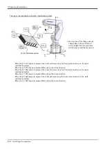
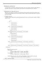
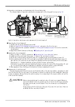
The installation summary of the solenoid valve is shown in
. Turn the controller’s power OFF before this
installing operation. Refer to
Page 49, "5.3.2 Installing/removing the cover"
for removing/ installing the cover.
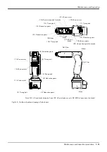
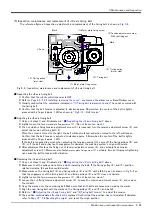
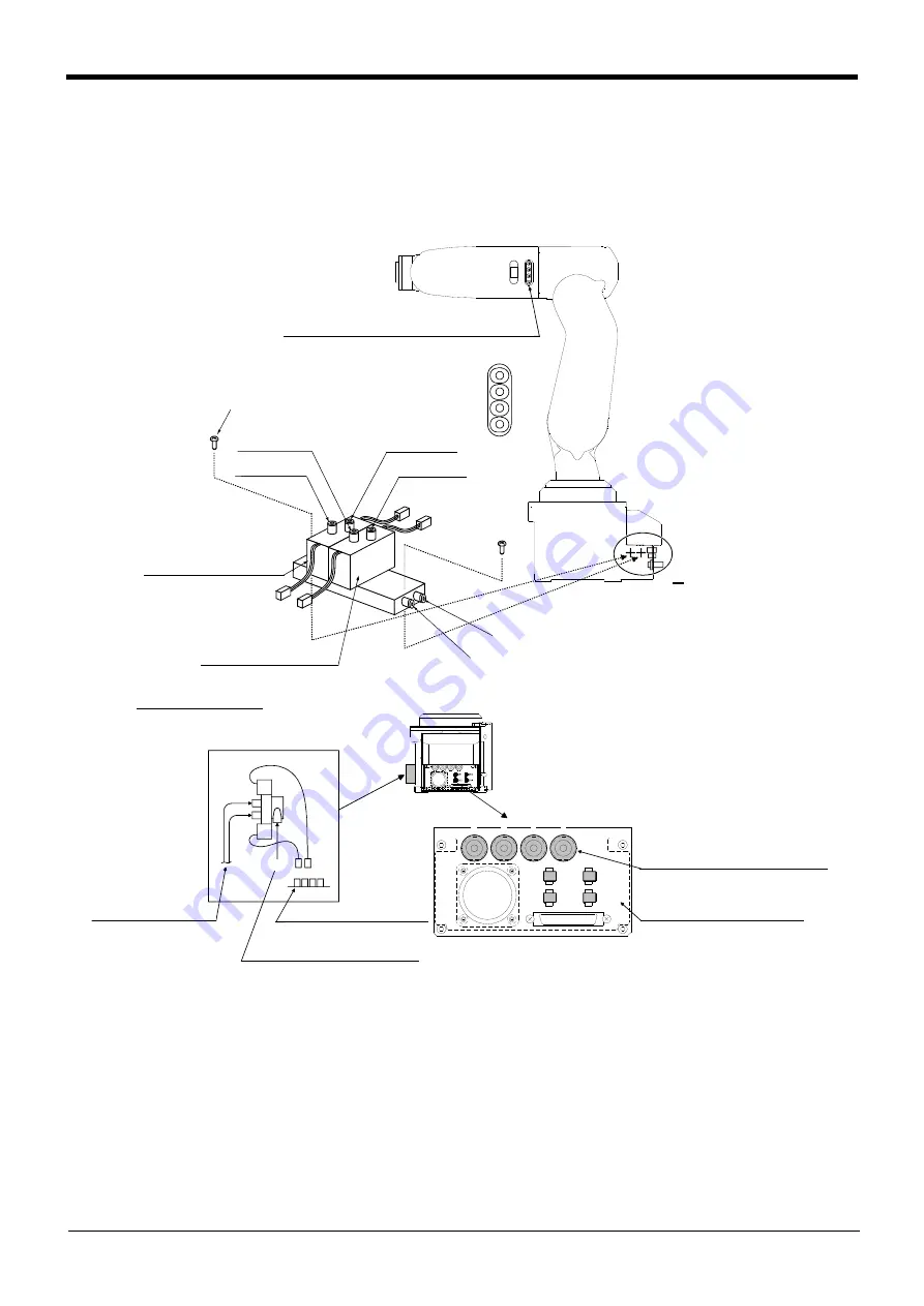
Fig.3-1 : Solenoid valve installation procedures
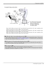
shows the solenoid valve installation procedures and the solenoid valve connector connection
procedures. The installation procedures are as follow. This work must be carried out with the controller power
turned OFF.
1) Using the screw holes on the base of the robot arm, install the solenoid valve with the enclosed screw <1>
(M3 x 25: 2 screws).
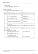
2) Connect the primary air supply air hose (φ6, prepared by customer) to the quick joint (P port) <2> of the
solenoid valve.
1~4 : 2次配管用継手
(φ4用)
電磁弁セット(オプション)
取付部分
ア
イ
2次配管エアホース
(φ4) 注1)
1次配管エアホース
(φ6×1本) 注1)
GR1~GR4 (イと接続)
ハンド出力用コネクタ
AIR OUT
1
2
3
4
⑧Bポート
GR2
GR 1
GR3
GR4
①Pナベネジ
(M3 × 25)
③第1電磁弁
⑦Aポート
④Aポート
⑤Bポート
Rポート
⑥第2電磁弁
②Pポート
A部
A部詳細
GR1~GR4 (イと接続)
ハンド出力用コネクタ
AIR IN 1~4 (アと接続)
2次配管用継手(φ4)
注1)電磁弁セットに接続するエアホースはお客様でご準備ください。
[拡大図]
1
GR1
2
3
4
GR3
GR2
GR4
<1>. P round head screw
R port
<2>. P port
[Expansion view]
The back of the robot-
arm base portion
1 ~ 4:Secondary piping pneumatic coupling
(φ4)
<4>. A port
<7>. A port
<8>. B port
<5>. B port
<3>. No.1 solenoid valve
<6>. No.2 solenoid valve
Solenoid value set (optional)
installation section
A
Detail of section A
Secondary piping
pneumatic hose
Note1)
AIR IN 1 to 4 (connect to <a>)
Secondary piping
pneumatic coupling (φ4)
<a>
<b>
GR1 ~ GR4 (connect to <b>)
Hand output connector
GR1 ~ GR4 (connect to <b>)
Hand output connector
Primary piping pneumatic hose Note1)
Note1) Please prepare by the customer the pneumatic hose to connect the solenoid valve set.
(φ6 x 1)
Summary of Contents for RV-2F Series
Page 2: ......


