Maintenance and inspection procedures 5-52
(2) Inspection, maintenance and replacement of J1-axis timing belt
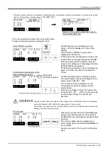
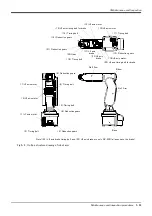
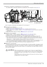
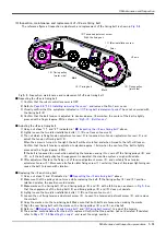
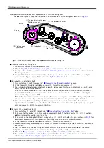
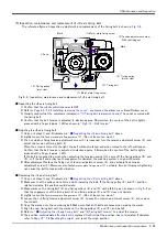
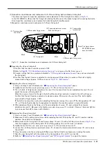
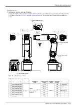
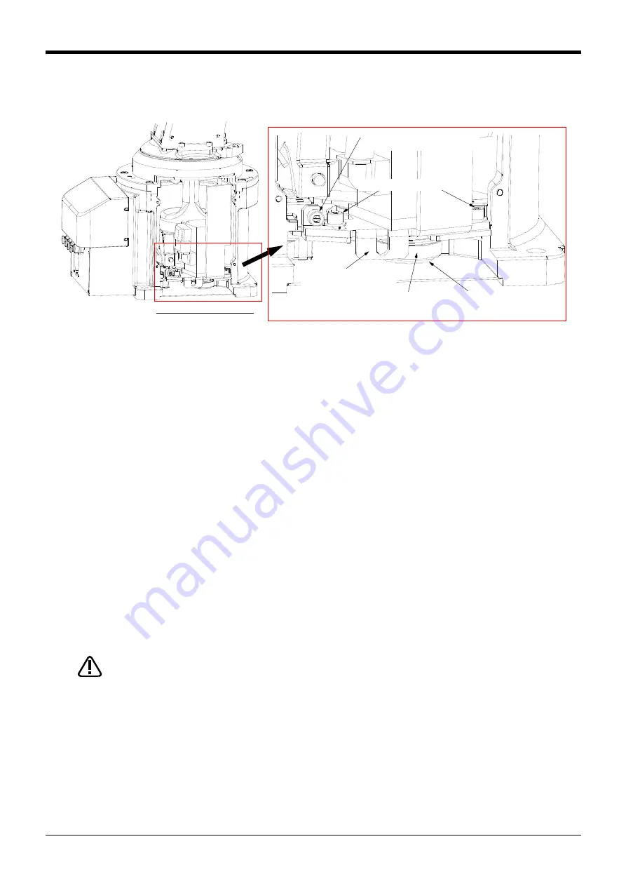
The reference figure at inspection, adjustment, and replacement of the timing belt is shown in
Fig.5-4 : Inspection, maintenance and replacement of J1 axis timing belt
■ Inspecting the J1 axis timing belt
1) Confirm that the robot controller power is OFF.
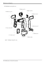
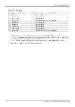
2) Refer to
Page 49, "5.3.2 Installing/removing the cover"
, and remove the J1 motor cover.
3) Visually confirm that the symptoms indicated in
"(1)Timing belt replacement period"
have not occurred with
the timing belt.
4) Adjust the belt with reference to following
" ■ Adjusting the J1 axis timing belt"
■ Adjusting the J1 axis timing belt
1) Carry out steps "1)" and "2)" indicated in
" ■ Inspecting the J1 axis timing belt"
2) Lightly loosen the motor plate fixing screw <1>.(two pc.) (Do not loosen too much.)
3) Loosen the nut fixing tension adjustment screw <3>. And lightly loosen tension adjustment screw <3>.
4) In the condition that hook <6> of the motor plate is pulled by 31-39N, fix the motor plate fixing screws <1>
tight. (two pc.) The tension of J1 axis timing belt is adjusted with this method. Certainly fix two motor plate
fixing screws <1>. Improper tightening can cause the belt to loosen with vibration.
If the belt is loosened too much when adjusting the tension causing it to come off the timing pulleys <4> and
<5>, or if the belt and pulley teeth engagement is deviated, the machine system's origin will deviate.
5) After adjustment, fixes the fixing nut and certainly fix tension adjustment screw <3>.
■ Replacing the J1 axis timing belt
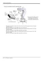
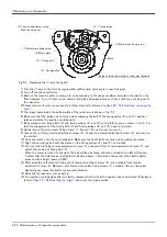
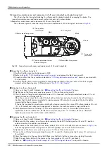
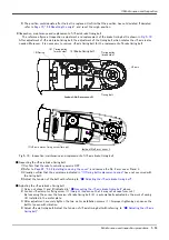
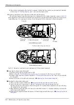
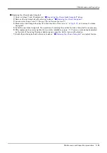
Timing belt replacement of the J1 axis removes the bottom plate in the robot-arm bottom, and replace the belt
from the robot's bottom. For this reason, it is necessary to remove the robot arm from the installation surface and
to place it sideways. Remove the machine cable or piping, etc. corresponding to the usage condition, and put the
robot on the floor sideways.
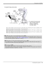
When removing and placing the robot arm, place J1 motor cover upward. Moreover,
also to turn the No.1 arm cover upward, turn the J1 axis to the front by jog operation
beforehand. (joint angle is near 0 degree) This is the necessity to not damaging the
resin cover.
Topple slowly so that a shock may not be given. If you have the resin cover, there is a
possibility that the cover may be broken.
Inside of J1 motor cover
<3>Tension adjustment screw
With the fixing nut
<1>Motor plate fixing screw
<2>Timing belt
<4>Timing pulley (near side)
<5>Timing pulley (back)
<6>Motor plate hook
Pulls and fixing
CAUTION
Summary of Contents for RV-2F Series
Page 2: ......

