8-35
Chapter 8 FUEL SYSTEM
3.1.1 Checking before installing fuel injection pump
(1)
When installing the right bank fuel injection pump,
rotate the crankshaft so that No. 1 piston is at the top
dead center of compression stroke, and when installing
the left bank fuel injection pump, rotate the crankshaft
so that No. 7 piston is at the top dead center of com-
pression stroke.
(2)
Remove the tentatively installed drive coupling and
laminated plates set on the drive coupling from the fuel
injection pump. Install the coupling and the set to the
accessory drive shaft with the woodruff key. Push the
drive coupling to the accessory drive as close as possi-
ble, and leave the tightening bolts loose.
(3)
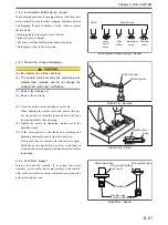
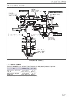
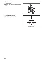
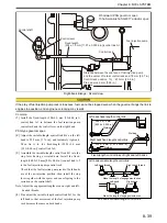
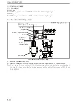
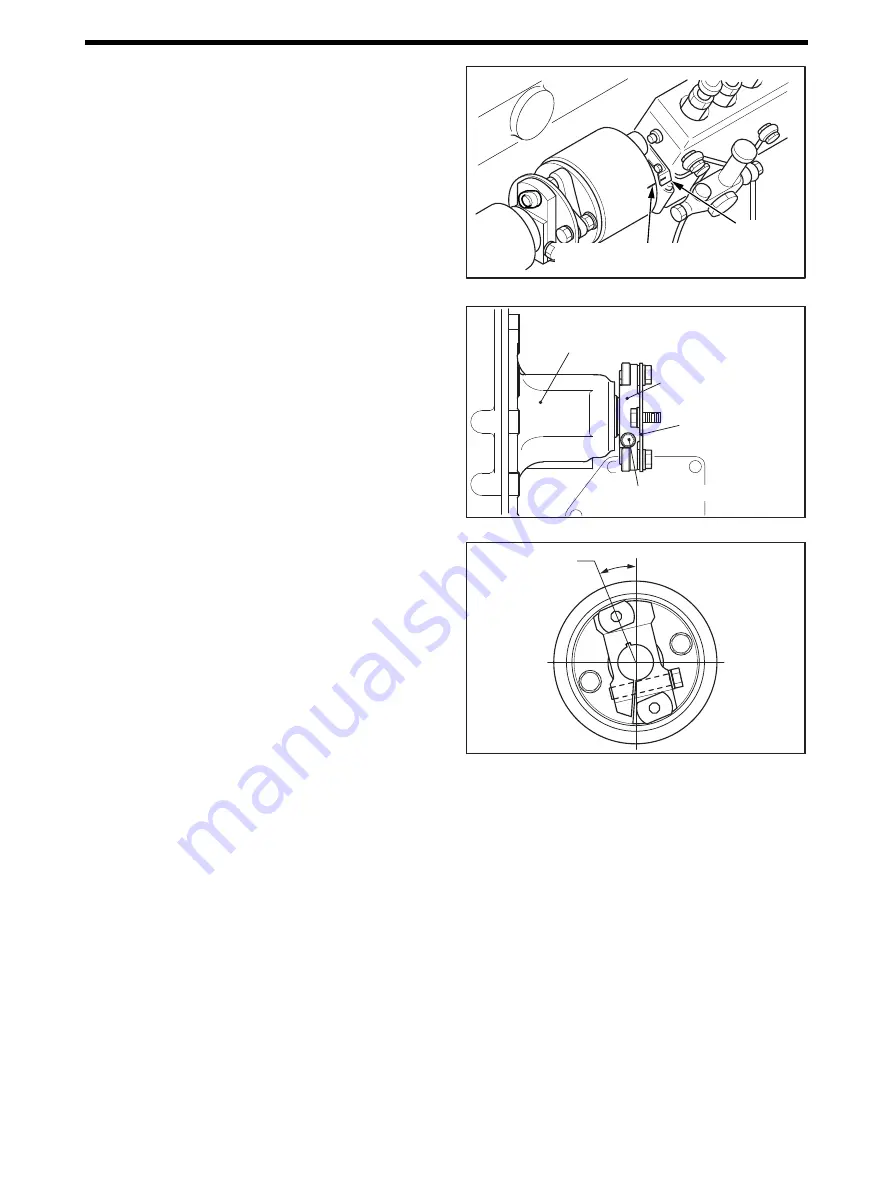
Align the line mark on the fuel injection pump coupling
(or timer) with the pointer.
(the injection start timings of cylinder No. 1 and No. 7)
Pointer and Line Mark - Align
Drive Coupling - Install
(4)
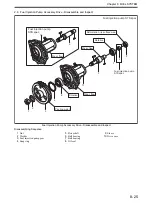
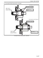
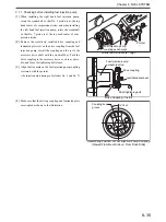
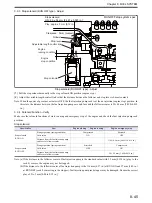
Make sure that the driving coupling and laminated plate
are coupled as shown in the illustration.
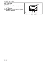
Assembling Position of Fuel Injection Pump Coupling
(Viewed From Rear Side i.e. From Drive Side)
Fuel injection pump
coupling punch mark
Pointer
Fuel injection pump
accessory drive
Drive coupling
Shaft tightening bolt
Laminated plate set
Coupling key
groove
19
°
30’±3
Summary of Contents for S12A2
Page 1: ...SERVICE MANUAL September 2010 Pub No 99269 20170 199269 20170 ...
Page 2: ......
Page 16: ......
Page 20: ......
Page 42: ......
Page 44: ......
Page 68: ......
Page 69: ...3 1 Chapter 3 SERVICE TOOLS 1 Special Tools 3 3 ...
Page 70: ......
Page 78: ......
Page 82: ......
Page 136: ......
Page 174: ......
Page 218: ......
Page 220: ......
Page 242: ......
Page 244: ......
Page 294: ......
Page 310: ......
Page 320: ......
Page 322: ......
Page 334: ......
Page 354: ......

