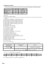
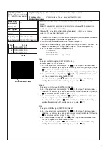
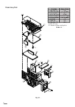
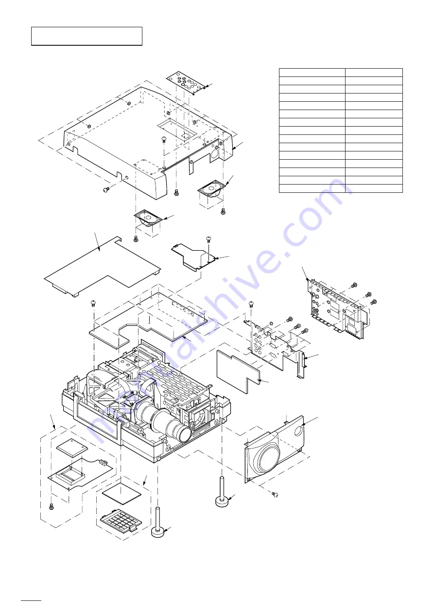
EXPOSED VIEW
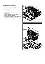
5
6
8
F
x2
I
x8
N
x2
O
x2
!0
!1
!2
!3
!4
!2
2
B
x2
1
C
x7
3
A
x3
E
x4
4
7
9
G
x1
H
x5
K
x2
J
x1
M
x6
L
x3
D
x4
P
x1
Q
x3
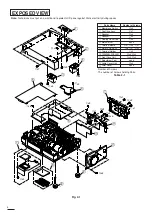
Fig. 2-1
Number of Screws :
The number of Screws holding Parts.
Table 2-1
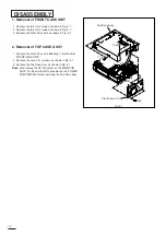
Note:
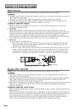
Technicians must put on a wrist band to protect LCD panel against Static electricity during repairs.
4
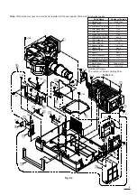
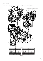
Parts Name
Number of Screws
q
Membrane Switch
A
x3
w
Top Case Assy
C
x7
e
Speaker
D
x4
r
Speaker
E
x4
t
Cooling Cover Top
F
x2
y
Main Barrier
none
u
Terminal Board
G
x1,
H
x5,
P
x1
i
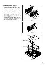
MAIN PCB ASSY
I
x8,
J
x1,
K
x2
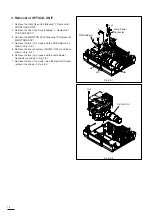
o
Terminal Holder
L
x3
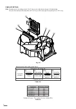
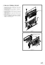
!0
TERMINAL PCB ASSY
M
x6,
Q
x3
!1
Front Case Unit
N
x2,
B
x2
!2
Adjustment Foot
none
!3
Lamp Cover Unit
O
x2
!4
Filter Cover
none
Summary of Contents for S290U
Page 83: ...16 ...
Page 180: ...113 SYMBOL NO ADDRESS X7A1 A 3 PCB MAIN COMPONENT SIDE ...
Page 188: ...121 ...


