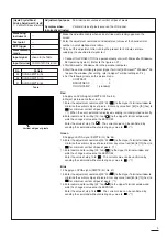
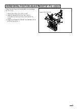
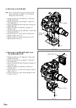
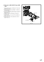
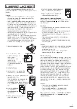
Follow the steps below for the adjustment after replacing
the ITG 1 Assy.
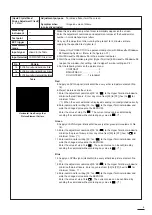
1. Project a full white raster on the screen.
2. Adjust the position of the ITG 1 Assy using a
screwdriver so that there is no unevenness on the
screen.
3. Apply SILICON BOND (TSE3941 No. 859D055O20) to
the ITG 1 Assy to fix it.
HORIZONTAL POSITION ADJUSTMENT OF ITG 1 ASSY
9
Apply SILICON BOND.
Summary of Contents for S290U
Page 83: ...16 ...
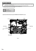
Page 180: ...113 SYMBOL NO ADDRESS X7A1 A 3 PCB MAIN COMPONENT SIDE ...
Page 188: ...121 ...


