a
x5
b
x6
c
x3
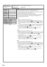
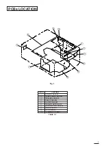
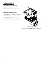
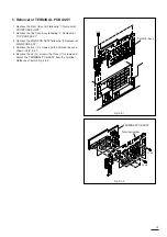
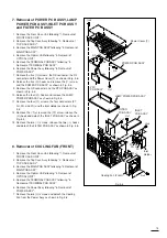
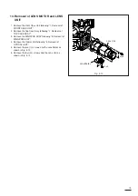
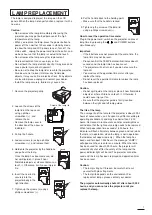
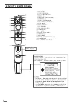
5. Removal of TERMINAL PCB ASSY
1. Remove the Front Case Unit following “1. Removal of
FRONT CASE UNIT”.
2. Remove the Top Case Assy following “2. Removal of
TOP CASE ASSY”.
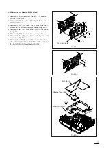
3. Remove the MAIN PCB ASSY following “3. Removal of
MAIN PCB ASSY”.
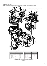
4. Remove the five (
a
) screws and the Terminal Assy as
shown in Fig. 3-4-1.
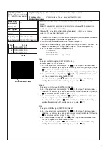
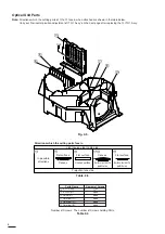
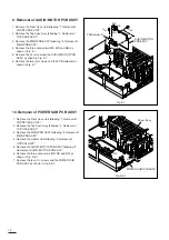
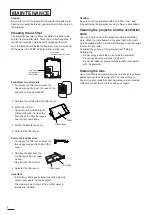
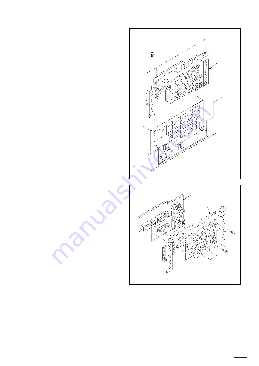
5. Remove the six (
b
) screws, the three (
c
) screws and
detach the TERMINAL PCB ASSY from the Terminal
Holder as shown in Fig. 3-4-2.
Terminal Assy
Fig. 3-4-1
TERMINAL PCB ASSY
Terminal Holder
Fig. 3-4-2
13
Summary of Contents for S290U
Page 83: ...16 ...
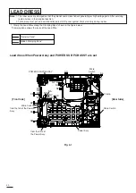
Page 180: ...113 SYMBOL NO ADDRESS X7A1 A 3 PCB MAIN COMPONENT SIDE ...
Page 188: ...121 ...


