Note:
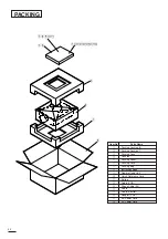
1. The inner wires are clamped so that they do not come close to heat generating or high voltage parts. After servicing
route all wires in their original position.
2. Technicians must put on a wrist band to protect LCD panel against Static electricity during repairs.
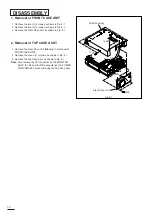
LEAD DRESS
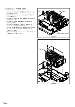
NB
SM
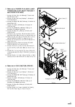
SP
SF
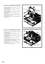
SA
RD
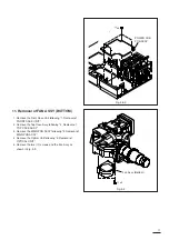
SD
RB
NY
NP
NA
NR
NM
NL
NF
NX
NC
NZ
NV
SC
SL
AL
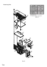
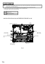
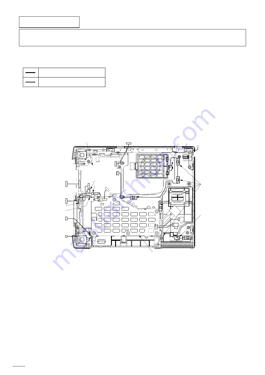
1. Clamp the Lead Wires along the Clamping Zone* shown in the figure below.
*Clamping Zone shows the route of the Lead Wire.
Clamping Zone*
Hidden Clamping Zone*
Fig. 4-1
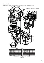
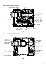
Lead dress When Power Assy and POWER SUB PCB ASSY are set
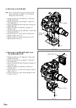
[Front Side]
Clamp
Micro
Switch
POWER SUB PCB ASSY
Power Assy
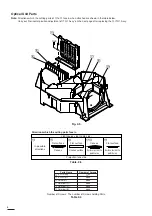
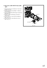
[Rear Side]
from the CN2 of
the Power Assy.
from the fan of the Power
Assy.
20
Micro Switch
Micro Switch
Summary of Contents for S290U
Page 83: ...16 ...
Page 180: ...113 SYMBOL NO ADDRESS X7A1 A 3 PCB MAIN COMPONENT SIDE ...
Page 188: ...121 ...


