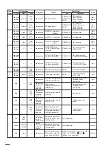
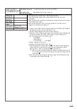

Adjustment purpose
[A/D Pre-Amplification Circuit]
1. Clamp Level
Symptom when
incorrectly adjusted
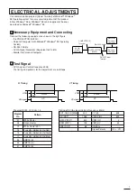
Measuring
instrument
Test point
EXT trigger
Measurement
range
Input signal
Input terminal
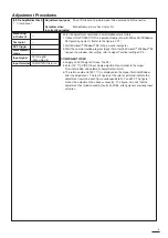
To set DC level of a picture signal to be entered to A/D converter.
Monochrome picture has a color tint.
---
---
---
---
SVGA signal
(Green,No.03)
COMPUTER IN terminal
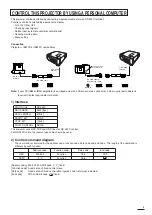
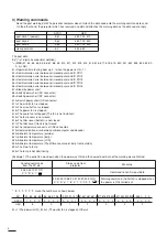
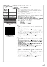
* Enter the adjustment command in small alphanumeric letters.
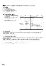
1. Connect this PROJECTOR to a personal computer (with Microsoft
Windows
95 Operating System). (Refer to the figure on P.1)
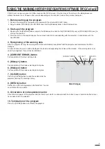
2. Start Microsoft
Windows
95 in the personal computer.
3. Start the communication program [Hyper Terminal] in Microsoft
Windows
95
to open the window. (For setting, refer to Hyper Terminal setting on P.2)
COMPONENT VIDEO
4. Supply an SVGA signal (Green, No. 03).
5. Enter [00~71] (VIDEO input clamp adjustment command) to the Hyper
Terminal window and automatic adjustment will start.
6. The return command [00~7111] is displayed on the Hyper Terminal Window
after the adjustment. The last 2 figures of the return command indicate the
adjustment result and each figure corresponds to R-Y and B-Y. The figure, 1
means the adjustment has been successful. The figure, 0 means that the
adjustment has failed caused by faults on PCBs, wrong signals or wrong input
selection.
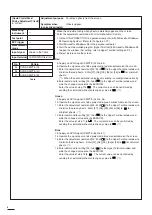
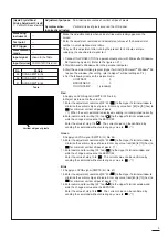
Adjustment Procedures
3
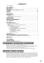
Summary of Contents for S290U
Page 83: ...16 ...
Page 180: ...113 SYMBOL NO ADDRESS X7A1 A 3 PCB MAIN COMPONENT SIDE ...
Page 188: ...121 ...


