Chapter 2 Installation and Setup
TDP-324
-22-
3.
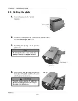
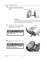
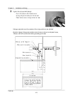
Tighten the screw and fix flange.
・
Turns in the direction of the illustration arrow,
applying a finger to the knob part of a fixed screw.
・
Please fasten securely, turning until the screw stops.
(
Flange set position and the relation of the range which can be printed
)
Relation between flange set position and print area is shown on diagram below.
Please confirm the print area before generating print data.
Example: The relation of the plate
and the range which can be
printed in the case of setting a
flange to "1" and using a plate with
a width of 324mm.
Print start side
Range which can be printed
When it sets to B
When it sets to A
When it sets to no-number
When you set the flange to 1
Summary of Contents for TDP-324
Page 1: ......
Page 2: ......
Page 4: ......
Page 54: ...Chapter 3 Use of Operation Panel TDP 324 48 MEMO...
Page 72: ...Chapter 4 Daily Maintenance TDP 324 66 MEMO...
Page 82: ...Chapter 7 After sales service TDP 324 76 MEMO...
Page 84: ...Chapter 7 After sales service TDP 324 78 MEMO...

