

Eng-4
En
g
lis
h
Mounting instructions
Wall-hole construction
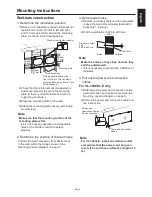
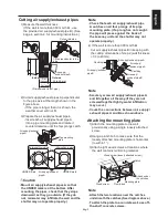
'HWHUPLQHWKHLQVWDOODWLRQSRVLWLRQ
Make sure to allow the required clearances (at
OHDVWPPRQWRSPPWROHIWDQGULJKW
DQGPPRQERWWRPDURXQGWKHPRXQWLQJ
plate, as shown in the drawing below.
* Nothing should obstruct the
IURQWRIWKHXQLW'RQRWSODFH
DQ\WKLQJEORFNLQJDLUÀRZLQIURQW
RIWKH/RVVQD\
&KHFNWKDWWKHUHLQIRUFHPHQWLQVLGHZDOOLV
positioned properly to secure the mounting
SODWH,IWKHUHLVQRUHLQIRUFHPHQWEXLOGLQD
supporting structure.)
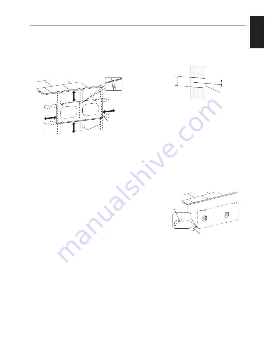
3) Place the mounting plate on the wall.
4) Attach the mounting plate loosely (with single
wood screw).
Note
Make sure that the mounting surface of the
PRXQWLQJSODWHLVÀDW
,ILWLVQRW/RVVQD\RSHUDWLRQFRXOGJHQHUDWH
noise or the shutter could not operate
properly.
2.
'HWHUPLQHWKHSRVLWLRQRIWKHZDOOKROHV
3RVLWLRQWKHZDOOKROHVDZD\IURPREVWUXFWLRQV
in the wall, within the ranges shown in the
mounting position diagram on page 3.
:RRGVFUHZIDVWHQORRVHO\
Mounting plate
5HLQIRUFHPHQW
At least
PP
At least
83 mm
At least
83 mm
At least
64 mm
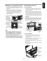
3. Drill the wall holes.
5HPRYHWKHORRVHO\IDVWHQHGPRXQWLQJSODWH
/HDYHWKHZRRGVFUHZORRVHO\IDVWHQHGLQ
SURFHGXUHLQSODFH
'ULOOWKHZDOOKROHVRI¡WR¡PP
Note
Make the holes so they slope down as they
exit the outside wall.
7KLVLVQHFHVVDU\WRSUHYHQWWKHLQ¿OWUDWLRQRI
rainwater.
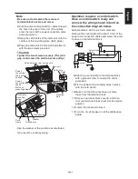
4. Pull out the power and connection
cables.
For VL-100EU
5
-E only
'HWHUPLQHWKHSRZHUDQGFRQQHFWLRQFDEOH
SXOORXWORFDWLRQDQGPDNHDKROH6HHWKH
mounting position diagram on page 3.)
2) Pull out the power and connection cables on
the indoor side.
Note
For VL-100U
5
-E, install an electrical outlet
somewhere that the power cord plug can
reach. (The cord has an effective length of 3
m.)
'LDPHWHURIZDOO
hole
¡WR¡PP
5°
Wall hole
Wall
Outside
Inside
Power and
connection cables
3XOORXWSRVLWLRQ
Power and connection
cables


