background image

DLP

TM 

Projector

VS-SH10U
Set-up and Installation Manual

August 30, 2002

Summary of Contents for VS-SH10U

Page 1: ...DLPTM Projector VS SH10U Set up and Installation Manual August 30 2002...

Page 2: ...tting 12 1 5 Buttons and functions of remote control unit 13 1 6 LED display 14 2 ADJUSTMENT MENU 15 2 1 Remote controllable items 15 2 2 Projector information display 15 2 3 Video memory select 15 2...

Page 3: ...3 4 Lamp pulling out 41 4 3 5 New lamp inserting 41 4 3 6 Lid attaching 41 4 3 7 Lamp timer confirmation 42 4 3 8 CSC calculating 42 4 3 9 Lamp exchanging 42 4 3 10 CSC manual adjustment 42 4 3 11 Gr...

Page 4: ...System Status 50 5 6 10 e Error Detection 51 5 6 11 ISA Lamp A Status 51 5 6 12 ISB Lamp B Status 51 5 6 13 ST1 Status Information 52 5 6 14 ST2 Lamp Timer Value 52 5 6 15 ST3 Set Timer Value 53 5 6...

Page 5: ...P P 5 positive 75 ohm Synchronous TTL level positive negative High level 2 5 5 0V Low level 0 0 5V Sync on green Video 0 7VP P 5 positive Synchronous 0 3VP P 5 negative Digital RGB video input Signal...

Page 6: ...distance 67 1000 2 21 1 mm 70 1047 4 22 0 mm 72 1078 9 22 7 mm 1 1 4 Mechanical Specification Optical Unit Circuit Box Width 500mm 150mm Height 300mm 300mm Dimensions Depth 300mm 200mm Weight 10kg 6Kg...

Page 7: ...ensing Temperature and humidity condition at storage 20 C 50 C 20 80 non condensing 1 1 7 Safety Approval Safety approval UL1950 CSA22 2No 950 EN60950 EMC FCC part15 Class A Industry Canada Class A EN...

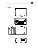
Page 8: ...First edition 8 1 2 Outline drawings 1 2 1 Circuit Box unit mm...

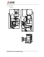
Page 9: ...VS SH10U Set up and Installation Manual 9 1 2 2 Optical Unit unit mm...

Page 10: ...Main power switch 2 AC socket 3 Status LED display 4 Wired remote control in 3 5 mini jack 5 Setup switch 6 RS 232C D SUB 9PIN M 7 Control IN D SUB 9PIN F 8 Control OUT D SUB 9PIN F 9 Digital IN MDR...

Page 11: ...e male male should be used to connect Pin assignment I O Signal Pin number IN terminal OUT terminal IN terminal OUT terminal 1 input output RXB TXB 2 input output RXA TXA 3 N C N C 4 output input TXB...

Page 12: ...RY Factory setting mode Standard SW 2 No Name ON OFF 8 ID5 7 ID4 6 ID3 5 ID2 4 ID1 Designating unit ID 1 to 32 ON 0 OFF 1 ID No 1x ID1 2x ID2 4x ID3 8x ID4 16x ID5 Example ID No 01 ID1 OFF ID2 to ID5...

Page 13: ...ss to display test patterns Press once for adjustment white Press twice for crosshatch Press 3 times for blue 180 Press 4 times for gray 30 Press 5 times for full bit white Normal Button Press to rese...

Page 14: ...D control circuit failure 4 Lamp changer control circuit failure 5 Internal SRAM failure 6 not defined 7 Power failure n No error Projector state display LED display Projector state Bar at center No s...

Page 15: ...99999H Lamp operating time LAMP A BUSY NEW Lamp A status LAMP B STANDBY NEW Lamp B status INPUT ANALOG DIGITAL Input select SYSTEM ID 1 32 Remote ID setting Red indications when remote ID is disable...

Page 16: ...B 2 7 Remote ID function Use the remote ID to operate the remote control toward specific projectors in the system Displaying remote control operability Press DISPLAY button Press FUNC DISPLAY button...

Page 17: ...ting V MASK Vertical sync mask position setting SEPARATE SYNC synchronizing input setting CLOCK setting DIV 1500 1800 1688 Sampling clock setting FINE 0 127 32 Sampling phase setting FREQ UNDER OVER 1...

Page 18: ...ITE BALANCE M GAMMA 2 DITHER ON CSC NORM APERTURE OFF NR OFF ENTER ENTER ENTER ENTER Initial image MENU1 MENU1 MENU1 MENU1 ESC ESC ESC ESC BRIGHT 0 WHITE BALANCE M CONTRAST 100 DITHER ON GAMMA 2 CSC N...

Page 19: ...ENTER ENTER ENTER AT W BUSY ESC ESC ESC ESC ENTER ENTER ENTER ENTER ENTER ENTER ENTER ENTER ESC ESC ESC ESC MEMORY 1 CLOCK POSITION CLAMP WHITE ADJUST V MASK SEPARATE SYNC W GAIN 255 128 R GAIN 255 12...

Page 20: ...adjustment SET WHITE BALANCE White balance adjustment SENSOR Luminous sensor setting LAMP PARAMETER Lamp parameter setting SET CSC menu NORMAL LAMP A Title R R 0 1023 1023 R G 255 0 R B 255 0 G R 255...

Page 21: ...ION menu R TOP 0 Top adjustment R BOTTOM 0 Bottom adjustment R LEFT 0 Left adjustment R RIGHT 0 Right adjustment R TOP LEFT 0 Top left adjustment R TOP RIGHT 0 Top right adjustment R BOTTOM LEFT 0 Bot...

Page 22: ...of error information is indicated Detailed error information code Bit15 Bit14 Bit13 Bit12 Bit11 Bit10 Bit9 Bit8 Bit7 Bit6 Bit5 Bit4 Bit3 Bit2 Bit1 bit0 bit0 error in lamp eject bit1 error in lamp ins...

Page 23: ...ESC ESC ESC NORMAL LAMP A B R 0 B G 0 B B 1023 NORMAL LAMP A R R 1023 R G 0 R B 0 NORMAL LAMP A G R 0 G G 1023 G B 0 ESC ESC ESC ESC ENTER ENTER ENTER ENTER ESC ESC ESC ESC or ENTER ENTER ENTER ENTER...

Page 24: ...E WARNING CHANGE MODE SENSOR SENSOR OFF SENSOR START SET WHITE BALANCE ESC ESC ESC ESC ENTER ENTER ENTER ENTER WHITE BALANCE M R GAIN 1000 G GAIN 1000 B GAIN 1000 ESC ESC ESC ESC ENTER ENTER ENTER ENT...

Page 25: ...SIGNAL DISPLAY NO SIGNAL display setting factory use only AUTO CLAMP START Auto clamp setting factory use only AUTO WHITE START Auto white level setting factory use only TEST BLANK Blanking on off set...

Page 26: ...OFF LEFT ON OFF RIGHT ON OFF BOTTOM ON OFF DISPERSION setting DISPERSION ON OFF GRADATION setting GRAD AUTO NONE SET APERTURE setting APERTURE 1 0 3 APERTURE 2 0 3 NO SIGNAL DISPLAY setting DISPLAY ON...

Page 27: ...RE 2 1 SET STANDARD CSC ESC ESC ESC ESC ENTER ENTER ENTER ENTER LAMP A SET OK VIEW STANDARD CSC CSC NORMAL R R 1023 R G 0 R B 0 Initial image ESC ESC ESC ESC FUNC FUNC FUNC FUNC G G G G ESC ESC ESC ES...

Page 28: ...T AT W BUSY AUTO CLAMP START TEST BLANK BLANK OFF NO SIGNAL DISPLAY ESC ESC ESC ESC ENTER ENTER ENTER ENTER DISPLAY OFF AT C BUSY ENTER ENTER ENTER ENTER ENTER ENTER ENTER ENTER ESC ESC ESC ESC ENTER...

Page 29: ...llation Manual 29 3 Set up and installation 3 1 Set up installation flow chart Start 3 3 Dip switch setting 3 4 Multiple screen color space control CSC adjustment 3 5 Video signal adjustment End 3 2 P...

Page 30: ...here are also the lines for overlap setting for reference They are located 5 pixels inside from both horizontal ends and 4 pixels inside from both vertical ends In the case of multi screen without ove...

Page 31: ...stment Adjust each axis with the hexagon wrench 3mm View from the screen Adjustment screw Clockwise Counterclockwise 1 Tilt the image 2 Form the vertical keystone distortion 3 Form the horizontal keys...

Page 32: ...one distortion adjust the image position to the center of the screen with V POSI 3 After forming the vertical keystone distortion adjust the image position to the center of the screen with H POSI 4 Ad...

Page 33: ...be adjusted only by increasing the black luminance level Input signal Built in test signal Black signal in the adjustment white Press TEST TEST TEST TEST button once and press R R R R G G G G B B B B...

Page 34: ...the tint finely by increasing or decreasing R R G G if the tint differs between each screen 10 Display magenta red plus blue and adjust the tint finely by increasing or decreasing R R B B if the tint...

Page 35: ...stment NOTE In principle this adjustment is unnecessary because the luminance tint level between each screen of the multi screen is adjusted in CSC adjustment Be careful not to deteriorate the uniform...

Page 36: ...right figure using adjustment item A and C at first then compensate it with B 4 Repeat the steps from 1 to 3 so as to uniform the luminance tint level of all colors 3 5 Video signal adjustment 3 5 1...

Page 37: ...torted Adjustment 1 Select V MASK in MENU2 2 Adjust so as to normalize the picture Set V MASK START at the maximum value which normalizes the picture Set V MASK END at the minimum value which normaliz...

Page 38: ...signal level is not in the adjustment range such as when the level of input video signal is too high or too low or full white signal is not input In such cases it is required to input the signal of th...

Page 39: ...the picture excessively deteriorates the tone characteristics of the darker part of the picture Press NORMAL NORMAL NORMAL NORMAL button to reset the value to the value adjusted before shipping from...

Page 40: ...ution Replace the lamp with as less pressure as possible on the optical engine not to swerve 6 axis adjustment Never look into the lamp while it is on Never touch the glass envelope of the lamp with y...

Page 41: ...replace and detach the lid 2 Confirm OPEN LED in operation panel is on 4 3 4 Lamp pulling out 1 Push EJECT button of relevant lamp in operation panel to pull out it till lamp cartridge is out of gear...

Page 42: ...ent on page 33 4 3 11 Gradation adjustment If necessary adjust gradation finely according to the procedure in Gradation adjustment on page 35 4 3 12 Lamp exchanging Lamp adjustment has finished Put ba...

Page 43: ...anual you have to measure it in SENSOR menu in service menu It should be measured 5 minutes after lamp turning on 1 It confirms lamp brown out by luminous sensor 2 It notices lamp changing preliminary...

Page 44: ...of lamp exchanging This message is displayed when the lamp is brown out It counts down from 5 to 0 then starts lamp exchanging 4 6 2 Operation time and error indication It can display error informati...

Page 45: ...command ID 00 is sent all connected projectors execute the command at once Only when the command ID corresponds with their unit ID or when the command ID is 00 Projectors execute the command 5 4 Seque...

Page 46: ...ues A CR code is added at the end of each result string The ID number and the command name shall not be delimited The ID number represents unit ID by two decimal digit ASCII characters When the projec...

Page 47: ...mode Response ID vP mode Current power control status 0 Termination process stand by mode mode 1 Start up process normal mode Note After completion of turning on it is desirable to issue other contro...

Page 48: ...projector does not respond to the mute caused by no signal 0 Mute cancel mute 1 Mute status 5 6 3 i Input Select Function To select display input port It is only available in steady state Format ID i...

Page 49: ...u change input port selection by remote control the memory selection might change It is only available in steady state Format ID nE Response ID nE 5 6 7 nA Analog Input Memory Select Function To chang...

Page 50: ...izing 9 Turning projector on 10 Turning DMD on 11 Reserved 12 Reserved 13 Steady state ready 14 Steady state 15 Steady state no signal 16 Reserved 17 Reserved 18 Lamp exchanging position setting proce...

Page 51: ...no error Format ID e Response ID e info Last detected error information 0 Fan stop 1 Lamp changer mechanical failure or no workable lamp 2 DMD control circuit failure 3 DMD control circuit failure 4...

Page 52: ...is uncertain value if p seq bit is 1 change 0 lamp exchanging prenotice off 1 lamp exchanging prenotice on mt 0 maintenance request off 1 maintenance request on The detailed maintenance request can be...

Page 53: ...I code time 000000 ffffff Set timer value Example If set timer value is 961 hours ID ST3 0003c1 r r stands for a CR code 0Dh 5 6 16 STR1 Lamp Timer Reset Function To reset lamp timer value Format ID S...

Page 54: ...1 mt0 mt0 error in lamp eject mt1 error in lamp insert mt2 reserved mt3 reserved mt4 sensor failure mt5 reserved mt6 reserved mt7 reserved mt8 reserved mt9 reserved mta not execute lamp initial positi...

Page 55: ...VS SH10U Set up and Installation Manual 55 6 Standard Installation Configuration 6 1 Optical unit Side view Top view...

Page 56: ...First edition 56 6 2 6 axis adjuster Model Screw holes VS SH10U c e h j...

Page 57: ...DMDTM Digital Micromirror DeviceTM are registered trademarks of Texas Instruments Microsoft Windows and Windows NT are registered trademarks of Microsoft Corporation The names of other products or com...

Page 58: ...First edition 58 8 Revision archive Description Revision date Issue first edition REV1 0 August 30 2002...

Reviews: